

Precision Fixturing for Modern Machine Shops
Posted by RMT on Sep 28th 2026
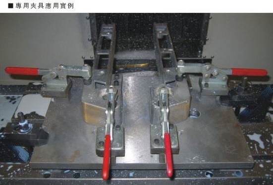
A toggle clamp can hold a part firmly and still be the wrong choice for a CNC fixture. Its position, direction of force, and clearance from the toolpath and loading route all matter; the clamp secures a correctly located workpiece but doesn’t replace sound locating and support. The fast, repeatable action makes toggle clamps for cnc fixtures useful for suitable manual-loading operations, but a clamp’s rated holding capacity isn’t the same as the clamping force applied to the part, and neither value alone confirms the setup is safe for machining. This article explains where manual toggle clamps fit, how vertical hold-down, horizontal hold-down, latch, and push-pull styles differ, and what to check when matching a clamp to the fixture layout and operation. You’ll also learn to assess tool access, workpiece support, mounting compatibility, and the manufacturer’s model-specific information before machining, so clamp selection is based on the actual setup rather than a capacity rating alone.
Key Takeaways
- Use the fixture to locate and support the workpiece; the clamp adds restraint but doesn’t replace proper location or support.
- Choose toggle clamps for cnc fixtures by comparing handle position, tool access, loading clearance, and the direction of motion required.
- Check a model’s published specifications, and don’t treat holding capacity as the clamping force applied to the part.
- Before machining, verify secure mounting, full linkage engagement, clear toolpaths, and repeatable workpiece seating.
Toggle Clamps in CNC Fixtures: Capabilities and Limits
Fixturing means locating, supporting, and securing a workpiece for an operation. A CNC machine fixture establishes the part’s position and supports it against machining loads; a toggle clamp adds restraint to help keep the part seated. It doesn’t correct poor location or make an unsupported workpiece rigid. The clamp is a fastening device, not a substitute for sound fixture design.
For toggle clamps for cnc fixtures, suitability depends on the machining operation, the fixture layout, and the verified specifications of the specific clamp model. In particular, don’t treat holding capacity and clamping force as interchangeable. Holding capacity is the manufacturer’s stated limit for the clamp; clamping force is the force applied to the workpiece. A capacity rating alone doesn’t show whether the part will remain seated under the forces and direction of a given cut.
How a toggle linkage holds a workpiece
The handle moves a linkage connected to the clamping element, such as a contact arm or plunger. As the handle closes, the linkage passes over center to reach a locked position. When properly engaged, that geometry resists the linkage opening under load without the operator holding the handle in place. The clamp’s contact point and alignment still matter: misalignment can shift the part or load the fixture unevenly.
Where toggle clamps fit in CNC workholding
For example, a fixture may locate a plate against fixed stops and support it on a base, while a hold-down clamp presses it toward those supports. The stops establish position; the supports resist deflection; the clamp supplies restraint. If cutting forces could lift, slide, or rotate the part, assess those directions and the full fixture setup rather than relying on the clamp rating alone.
Ridiculous Machine Tools offers manual toggle clamp configurations for different fixture needs. Check each model’s published holding capacity, contact arrangement, and mounting requirements before deciding it suits the operation.
Choose a Toggle Clamp Style for Fixture Access and Motion
Clamp style affects more than how the workpiece is restrained. The handle’s travel, the clamping element’s path, and the space occupied by the clamp all shape operator access, loading clearance, and tool access. For toggle clamps for cnc fixtures, compare the locked and open positions against the full fixture envelope and programmed toolpath, not just the clamp’s footprint.
Horizontal versus vertical hold-down arrangements
A vertical hold-down toggle clamp generally has a handle that stands upright when locked. That arrangement may suit a fixture with room above the clamp, but check for interference with the operator’s hand, adjacent tooling, and machine clearance. A horizontal hold-down toggle clamp keeps its handle generally low when locked. It may help where overhead space is limited, though the handle still needs a clear path to open and close. Review horizontal manual toggle clamps and vertical manual toggle clamps by model, including mounting and contact details.
When latch or push-pull designs may fit
A latch toggle clamp uses a hook or similar component to pull two parts together, which can suit a fixture that closes across a gap. A push-pull straight-line clamp moves its plunger linearly, so consider it when the fixture needs a direct pushing or pulling action. Neither configuration is suitable by name alone; confirm that its travel and contact geometry match the fixture.
| Configuration | Motion | Potential fit | Verify |
|---|---|---|---|
| Horizontal hold-down | Hold-down; handle stays low when locked | Limited overhead envelope | Handle sweep, tool clearance, mounting |
| Vertical hold-down | Hold-down; handle stands upright when locked | Clear overhead access | Handle height, loading path, mounting |
| Latch | Hook pulls components together | Closing across a gap | Hook engagement, travel, fit |
| Push-pull straight-line | Plunger moves linearly | Direct push or pull action | Stroke, contact direction, mounting |
Use the table to narrow the layout options, then confirm the chosen model’s published specifications against the operation.
Size and Position CNC Fixture Toggle Clamps Using Verified Requirements
Choose toggle clamps for cnc fixtures by working through the part and fixture requirements in order, then checking the exact clamp model’s published information. A category name or capacity figure alone can’t establish suitability for a machining operation.
- Confirm workpiece location. Identify the datums and stops that establish the part’s position.
- Plan clamp contact. Place the contact point so the clamp presses the part toward its locators and supports, without distorting or destabilizing it.
- Check access. Review the clamp’s open and locked positions against the toolpath, tool changes, loading route, and chip removal.
- Verify mounting. Confirm the model’s base style and mounting requirements suit the fixture plate and available fasteners.
- Review model specifications. Check the product information for the specific model’s stated holding capacity, material, base, spindle, and mounting details.
Check contact, clearance, and workpiece support
A clamp contacting a thin or unsupported area can bend the workpiece or shift it away from a datum. Place the clamp over adequate support and assess whether its contact direction resists the expected movement. Check the full toolpath, including approach and retract moves, and ensure the clamp doesn’t obstruct loading or trap chips where they could affect seating.
Read model-specific capacity and mounting data
Holding capacity is the manufacturer’s stated limit for the clamp; it isn’t the clamping force applied to the workpiece. Cutting forces act on the part through the operation and can vary in direction and effect. Don’t treat a static capacity rating as proof that a setup can withstand those forces. If loads, part stiffness, or force paths are uncertain, have a qualified fixture engineer assess the application rather than relying on a universal calculation.
Ridiculous Machine Tools publishes model-specific details across its manual toggle clamp options. Review the applicable model information before selecting a clamp or approving the fixture for machining.
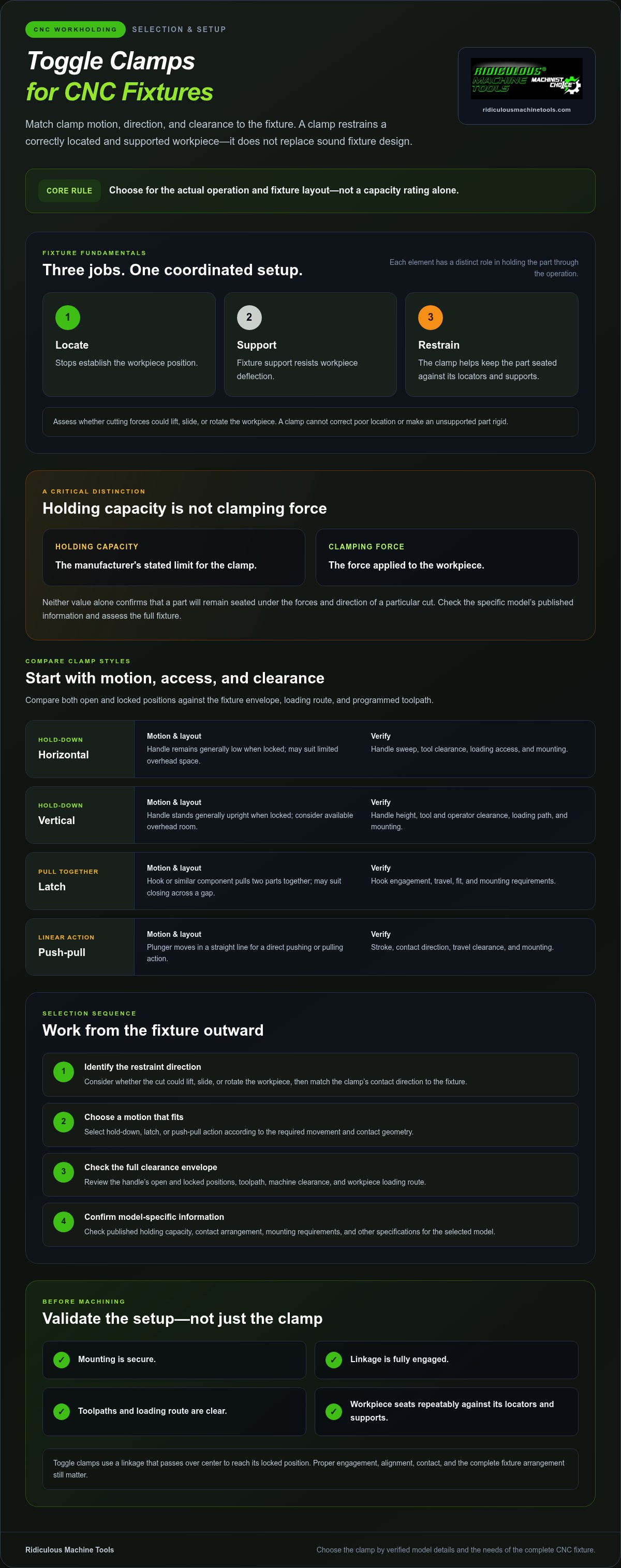
Set Up and Validate Toggle Clamps Before CNC Operation
A clamp that fits the fixture layout still needs a setup check before the cycle begins. Verify that the clamp is secure, engages fully, and holds the workpiece against its locators and supports. A repeatable handle position is useful only if the part also seats consistently.
A practical pre-run fixture check
- Inspect mounting. Check that the clamp base and fasteners are secure, and look for looseness or visible damage.
- Operate the linkage. Move the handle through its full travel. Confirm that the clamping element contacts the intended surface and the linkage reaches its locked position without binding.
- Confirm seating. Load and secure the workpiece, then check that it rests against its locators and supports. Watch for rocking, shifting, or a gap at a locating surface.
- Check clearance. Compare the clamp in its locked position with the programmed toolpath, tool changes, and machine movement. Account for the clamp’s full envelope, not only its contact point.
- Inspect condition. Look for wear, deformation, or damage that could affect engagement or contact. Follow the clamp and fixture manufacturers’ instructions for use, inspection, and maintenance.
If the part doesn’t seat repeatably or the clamp doesn’t engage as intended, stop and correct the setup before machining. Confirm the workpiece remains located and supported, and follow the machine manufacturer’s operating and safety instructions. For workshops integrating advanced rotary tables or automated fixtures requiring reliable electrical and signal transmission across moving axes, discover TME Systems Pty Ltd to source industrial slip rings.
Find a clamp category that matches the layout
Handle orientation, contact style, and linkage motion help narrow the configuration, but they don’t establish that a clamp suits a specific cut. Ridiculous Machine Tools offers manual toggle clamps in several configurations. Review the available types and verify each model’s specifications against the fixture and operation before selection.
Make the Clamp Choice Fit the Fixture
Effective workholding starts with a fixture that locates and supports the part. A toggle clamp adds restraint; its style and position must suit the loading path, tool access, and machining forces. For toggle clamps for cnc fixtures, distinguish the manufacturer’s holding-capacity rating from the clamping force applied to the workpiece, then verify the actual model specifications.
Before a cycle, confirm the clamp is securely mounted and fully engaged, the workpiece seats repeatably against its locators, and the clamp clears the programmed toolpath. Ridiculous Machine Tools offers horizontal, vertical, latch, and push-pull manual toggle-clamp categories. Specifications vary by model, so check the applicable product page for capacity, material, base, spindle, and mounting details rather than assuming one model’s information applies to another.
Review Ridiculous Machine Tools manual toggle clamps and verify model specifications to compare available configurations against your fixture requirements. A deliberate fit check helps you move forward with greater confidence in the setup.
Frequently Asked Questions
What is a toggle clamp used for in a CNC fixture?
A toggle clamp applies manual restraint to a workpiece after the fixture locates and supports it. In toggle clamps for cnc fixtures, the clamp can help hold a part against stops or other locating features during a suitable operation. It doesn’t establish the part’s position or replace adequate support. Its style and contact point should fit the fixture layout, loading path, and machining requirements.
Can toggle clamps hold a workpiece during CNC machining?
Yes, a toggle clamp can be suitable for some CNC machining operations if the clamp, fixture, and workpiece are appropriate for the loads involved. Suitability depends on the cut, workpiece stiffness, support, clamp position, and model specifications. Verify the setup rather than relying on a capacity rating alone. For uncertain or demanding loads, seek qualified fixture-engineering review before machining.
How do I choose between horizontal and vertical hold-down toggle clamps?
Choose based on the handle position and available space in both the locked and open states. A vertical hold-down clamp has a handle that is generally upright when locked, so check overhead clearance and operator access. A horizontal hold-down clamp keeps the handle generally low, which may suit a restricted overhead envelope. In either case, check tool access, loading clearance, and the model’s mounting details.
How is toggle-clamp holding capacity different from clamping force?
Holding capacity is the manufacturer’s stated limit for the clamp. Clamping force is the force the clamp applies to the workpiece. They describe different things, so don’t use a capacity figure as though it directly states the force on the part or proves machining suitability. Review the exact model information and assess the operation’s forces and fixture arrangement before relying on the clamp.
Where should toggle clamps be positioned on a CNC fixture?
Position clamps so their contact presses the workpiece toward its locators and supports, without bending or destabilizing it. Check that each clamp clears the toolpath, tool changes, loading route, and chip removal area in its open and locked positions. The part should seat repeatably against its locating features. If force direction or workpiece support is uncertain, have the fixture assessed before use.
Article by
Ridiculous Machine Tools Technical Team
The Ridiculous Machine Tools Technical Team provides practical information about precision machine tooling, CNC tooling, workholding, and related manufacturing applications. RMT focuses on helping machinists, manufacturers, fabricators, and other customers understand tooling specifications, compatibility, selection, and proper application. Our technical content draws on product specifications, industry knowledge, and RMT's quality-control experience to provide clear, useful information for selecting and using machine tooling and workholding products.
Ridiculous Machine Tools — Machinist's Choice™