

Tool Holding: Precision Machining Selection Guide
Posted by RMT on Sep 22nd 2026
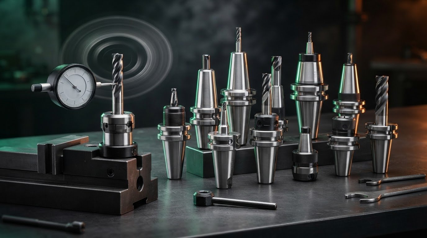
According to research from the Society of Manufacturing Engineers, every 0.0001-inch increase in Total Indicated Runout (TIR) degrades solid carbide end mill life by roughly 10 percent. When you fight excessive tool deflection, chatter during heavy cuts, or premature flute wear, the root cause rarely stems from your machine spindle or programming alone. Matching application-specific tool holding solutions to your cutting dynamics is the most direct path to eliminate runout, maximize clamping force, and achieve repeatable machining tolerances below 0.0002 inches.
You already know the frustration of watching expensive carbide tools chip because a holder failed to maintain rigidity under radial loads. Master industrial tool holding selection to eliminate runout, maximize rigidity, and hit sub-thousandth tolerances on every setup. This guide breaks down the mechanical differences between ER collet chucks, solid end mill holders, and steep taper interfaces so you can specify the exact tooling needed for roughing versus finishing.
Key Takeaways
- Deploying purpose-matched tool holding solutions balances mechanical clamping force with concentricity to stop chatter and prevent uneven carbide flute wear.
- Differentiate your setup strategy by reserving solid end mill holders for heavy roughing cuts and high-precision ER collets for finishing passes.
- Certified G2.5 dynamic balancing at 30,000 RPM protects machine spindle bearings and prevents destructive harmonic vibrations at elevated surface footage.
- Standardize setup procedures with dedicated CNC tightening fixtures and calibrated torque values to maintain repeatable runout below 0.0002 inches TIR.
- Cut out layered industrial distributor markups by purchasing production tooling directly from manufacturers with verified quality-control certification.
Fundamentals of CNC Tool Holding: Mechanics, Rigidity, and Runout
A CNC toolholder forms the structural bridge transmitting motor torque and spindle clamping force directly to the cutter. When this mechanical connection lacks rigidity, cutting accuracy collapses immediately. Machining forces trigger deflection, which creates chatter, ruins surface finishes, and damages spindle bearings. Selecting production-grade tool holding solutions ensures that radial and axial cutting loads transfer cleanly through the spindle housing rather than flexing the cutting tool.
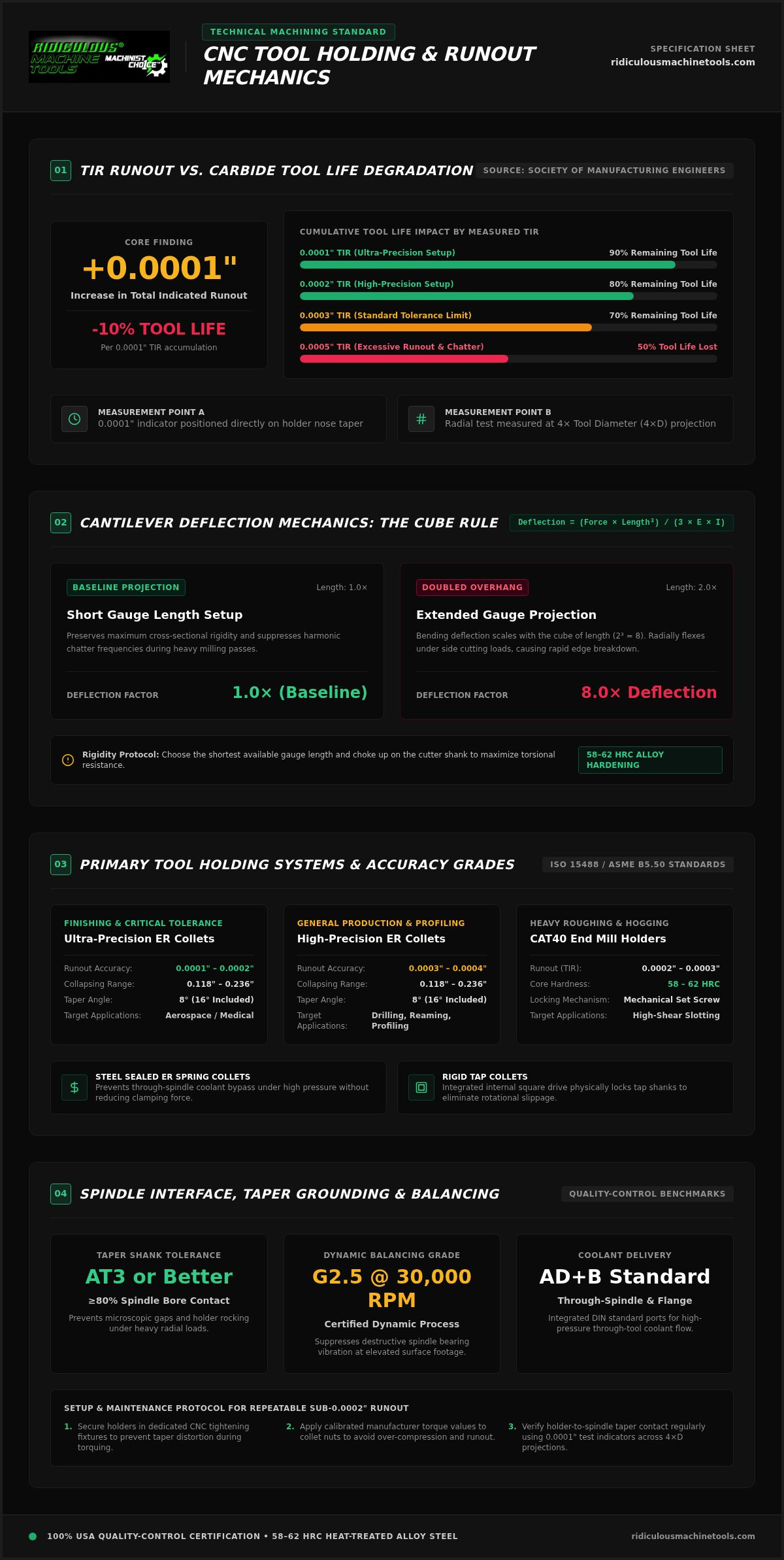
Every 0.0001-inch increase in Total Indicated Runout (TIR) reduces solid carbide end mill life by roughly 10 percent. Concentricity errors force a single cutting edge to take an oversized chip load while opposing flutes cut air. This uneven chip load accelerates micro-fracturing along the carbide edge, resulting in premature failure.
The Mechanics of Total Indicator Reading (TIR)
Total Indicated Runout measures rotational deviation from a true central axis. Check radial runout using a 0.0001-inch test indicator at two positions: on the holder nose taper and at a projection distance of four times the tool diameter (4×D). Standard steep tapers, including CAT40 and CAT50 shanks, follow standard machine tool taper interfaces governed by ASME B5.50. Holders ground to AT3-or-better taper shank tolerances deliver at least 80 percent surface contact with the spindle bore. Inferior taper tolerances create microscopic gaps, allowing the holder to rock under radial load and multiplying runout down the length of the tool shank.
Torsional Rigidity vs. Radial Deflection
Tool deflection is governed by cantilever beam mechanics. The equation for beam deflection proves that bending increases with the cube of overhang length:
Deflection = (Force × Length3) / (3 × Modulus of Elasticity × Moment of Inertia)
- Overhang length: Doubling gauge length multiplies radial deflection by eight times under identical side cutting loads.
- Cross-sectional mass: Thicker holder bodies resist torsional twist during high-shear slotting and aggressive profiling.
- Setup protocol: Choke up on the cutter shank. Choose the shortest gauge length available in your tool holding solutions to preserve cross-sectional rigidity and suppress chatter frequencies.
Pairing heat-treated alloy steel holders hardened to 58-62 HRC with short tool projections prevents elastic deformation during heavy milling passes. Maintaining high radial stiffness stabilizes the cutting path, keeping part dimensions well within sub-thousandth production tolerances.
Comparing Primary Tool Holding Systems: Collets vs. Solid Holders
Every machining operation demands a conscious trade-off between runout concentricity and positive retention. Solid end mill holders lock a tool mechanically to prevent axial movement under aggressive hogging. Collet systems wrap 360 degrees around the shank, maximizing surface contact and minimizing rotational runout for precise contouring. Successful CNC shops don't treat holders as generic hardware. They evaluate cutting dynamics, radial forces, and operating speeds before clamping a cutter.
As demonstrated in NIST research on tool-holder-spindle dynamics, the mechanical coupling between holder and tool directly establishes dynamic stability limits and harmonic chatter thresholds. Matching the right tool holding solutions to your roughing and finishing paths stabilizes cutting forces across every pass.
ER Spring Collet Systems for Concentricity and Versatility
ER collets follow the ISO 15488 standard with an 8-degree taper (16-degree included angle), providing uniform circumferential grip across cylindrical shanks:
- High-precision ER collets: Maintain 0.0003 to 0.0004 inch accuracy with a 0.118 to 0.236 inch collapsing range, ideal for general drilling, reaming, and light profiling.
- Ultra-precision ER collets: Deliver 0.0001 to 0.0002 inch runout for tight-tolerance aerospace or medical finishing.
- Steel sealed ER spring collets: Prevent high-pressure through-spindle coolant bypass without degrading clamping force.
- Tap collets: Feature an integrated internal square drive that physically locks the tap shank, preventing slippage during rigid tapping cycles.
To support high-pressure setups, RMT ER collet chucks integrate DIN 69871 Form AD+B coolant through the spindle and flange configuration as standard equipment.
Solid End Mill Holders for Maximum Roughing Security
Side-lock end mill holders use a precision-ground bore and a hardened set screw that engages directly with a tool's Weldon flat. This positive physical stop prevents high-helix cutters from creeping out of the pocket under heavy axial loads. RMT CAT40 end mill holders feature precision-ground bores holding 0.0002 to 0.0003 inch TIR and are case-hardened to 58-62 HRC. This heat treatment stops the inner bore from bell-mouthing under severe shock loads during interrupted roughing cuts.
Morse and Jacobs Taper Adapters for Secondary Operations
Secondary operations benefit from direct taper seating. Morse taper adapters let you mount heavy-shank drill bits and reamers straight into production spindles, minimizing stack-up tolerances. Jacobs taper adapters secure keyless drill chucks and tapping heads for high-mix batch setups. Precision-ground taper interfaces deliver rigid torque transfer and prevent radial slippage during heavy axial drilling passes.
Explore production-grade toolholders and collets by reviewing the lineup at ridiculousmachinetools.com to equip your CNC spindles for repeatable accuracy.
Spindle Harmonics and Dynamic Balancing Standards at High RPM
Centrifugal force multiplies exponentially with rotational velocity. The governing physical relationship, F = m × ω2 × r, dictates that doubling spindle RPM quadruples the radial force exerted by any off-center mass. At 15,000 to 30,000 RPM, an unbalance of just a few gram-millimeters exerts violent centrifugal loads against precision spindle bearings. This mechanical unbalance triggers severe harmonic vibration, degrades Ra surface finishes with chatter ripples, and causes premature spindle failure. High-velocity milling demands precision-balanced tool holding solutions that keep dynamic runout locked down under load.
Understanding ISO Dynamic Balancing Grades
Rotor balance tolerances are defined internationally by ISO 21940-11 (which superseded ISO 1940-1). For high-performance CNC tool assemblies, Grade G2.5 represents the industrial benchmark. Permissible residual unbalance is calculated using the operating speed:
eper = (G × 9549) / n
In this formula, G is the balance grade (2.5 mm/s) and n represents the maximum operating spindle speed in RPM. Symmetrical tool body geometry, precision-machined drive slots, and uniform wall thickness eliminate heavy spots before balancing. RMT dynamically balances toolholders to Grade G2.5 at 30,000 RPM. Each holder includes a certified dynamic balancing inspection sheet verified by 100% USA quality control, preventing harmonic spikes when your spindle ramps to maximum velocity.
Through-Spindle Coolant Delivery and Flange Features
Internal coolant management plays a direct role in spindle balance and cutting efficiency. Asymmetrical fluid distribution inside an unbalanced toolholder introduces dynamic instability during high-velocity rotation. RMT ER collet chucks integrate DIN 69871 Form AD+B dual-delivery capability directly out of the box:
- Form AD delivery: Channels high-pressure coolant straight through the spindle center and retention knob, clearing chips directly at the tool point during deep pocketing.
- Form B delivery: Reconfigures flow through twin peripheral ports on the drive flange, providing targeted external wash for machines without through-spindle coolant drawbars.
- Balanced fluid passages: Symmetrically ground internal fluid channels prevent off-center coolant weight distribution, preventing fluid-induced harmonic vibration during high-RPM passes.
Integrating certified G2.5 balancing with Form AD+B coolant ports ensures your tool holding solutions flush chips cleanly while running smooth at 30,000 RPM.
Proper Setup, Maintenance, and Torque Control for Tool Holders
Precision toolholder bodies cannot compensate for sloppy assembly practices. Even top-tier tool holding solutions lose their concentricity when an operator tightens a collet nut by feel or seats a taper covered in dried coolant residue. Micron-level accuracy requires strict physical protocol at the setup bench. Controlling clamping torque, using dedicated assembly fixtures, and enforcing clean taper contact surfaces protects repeatability across high-volume production runs.
Correct Collet Assembly and Torque Management
Assembly sequence dictates final concentricity. Always snap the ER collet into the nut's eccentric extractor ring at an angle before threading the nut onto the chuck body. Dropping a collet loosely into the chuck pocket and cranking the nut down jams the 8-degree taper cockeyed, permanently ruining its collapsible slots.
Never rely on open-ended hand wrenches. Under-tightening allows cutting forces to yank the tool shank out of the pocket during heavy profiling cuts. Over-tightening crushes the collet taper, galling the nut threads and generating runout well above 0.001 inches TIR. Tighten collet assemblies with a calibrated torque wrench to the exact foot-pound rating specified for that ER frame size.
Safe Off-Machine Assembly with Tightening Fixtures
Never tighten toolholders while they sit clamped inside a CNC machine spindle. Applying high manual torque directly to a spindle-seated toolholder side-loads the drive dogs and brinnells high-precision spindle bearings. Set up your tooling on a dedicated workbench benchtop instead.
- Two-way locking: A bench-mounted Universal CNC Tightening Fixture locks steep-taper flanges mechanically in both horizontal and vertical positions.
- Operator safety: Positive mechanical clamping stops the holder body from spinning when an operator breaks loose stubborn high-torque retention nuts.
- Secure fastening: Clamping the flange rigidly prevents radial slipping, protecting taper ground surfaces from scuffs and scratches.
Taper Cleaning and Inspection Protocols
Foreign debris between matching steel tapers acts as a mechanical pivot. A solitary 5-micron chip trapped between an AT3 spindle taper and a CAT40 tool shank angles the toolholder body outward, multiplying runout past 0.0008 inches at a 4-inch tool projection length. Wipe down tool shanks and machine spindle pockets using lint-free wipers and dedicated taper-wiper cleaners before every insertion.
Inspect tapers weekly for signs of fretting corrosion, deep scratches, or bore bell-mouthing. Run a 0.0001-inch dial test indicator inside the empty holder taper to audit internal concentricity before loading high-value carbide tooling.
Eliminate assembly errors and safeguard your machine spindle bearings by investing in a bench-mounted fixture directly through ridiculousmachinetools.com.
Selecting Reliable Production Tooling: The Direct Supplier Advantage
High-mix machine shops cannot afford production delays caused by backordered parts or layered distributor channels. Traditional tooling procurement routes pass products through regional sales reps and intermediate warehouses, piling on distribution fees and obscuring batch traceability. Buying tool holding solutions directly from a specialized manufacturer eliminates middleman overhead, provides fast inventory delivery, and guarantees immediate access to factory technical data.
Spindle rigidity alone won't save a part if your workpiece shifts under heavy cutting pressure. Pairing high-tolerance spindle chucks with reliable workholding hardware like horizontal toggle clamps establishes end-to-end rigidity throughout your CNC machine fixture, keeping raw stock locked in a fixed position under extreme shear loads.
Quality Assurance Standards for Production Toolholders
Never rely on catalog claims that lack verifiable inspection data. Production machining requires verified metallurgy and certified mechanical runout checks:
- 100% USA quality-control certification: Every toolholder body and collet undergoes rigorous bench testing to confirm geometric concentricity and dimensional accuracy before shipping.
- Heat treatment standards: Alloy steel bodies are case-hardened to 58-62 HRC, preventing pocket deformation, set screw stripping, and premature taper fatigue.
- Certified taper and runout limits: AT3 or better taper shanks ensure tight spindle contact, while ER16 CAT40 collet chucks guarantee 0.0001 to 0.0002 inches TIR for continuous high-tolerance milling.
Matching Holder Selection to Machine Shop Priorities
Standardizing spindle interfaces streamlines shop floor efficiency. Consolidating around CAT40 or CAT50 platforms reduces the variety of pull studs, wrenches, and spare collet sets needed across your tool crib. Equipping your vertical and horizontal machining centers with certified G2.5 balanced chucks protects spindle bearings during high-RPM cycles, reducing long-term maintenance costs and keeping surface finishes consistent across long part runs.
With over three decades of practical industry experience across aerospace, automotive, energy, and medical manufacturing, direct procurement guarantees technical accuracy for every setup. Contact the tooling specialists at Ridiculous Machine Tools to outfit your machine shop with certified tool holding solutions engineered for repeatable precision.
Lock In True Machining Tolerances on Every Setup
Holding sub-thousandth tolerances across heavy production runs requires removing mechanical uncertainty at the spindle nose. Controlling runout protects expensive carbide cutting flutes, while assigning solid holders to roughing and precision ER collets to finishing stabilizes radial chip loads. Running assemblies with dynamic G2.5 balancing certified to 30,000 RPM protects spindle bearings, while hardened 58-62 HRC alloy steel construction prevents taper bore distortion under relentless production demands.
With over three decades of shop floor machining experience, the technical team at Ridiculous Machine Tools verifies every assembly with 100% USA quality-control testing to deliver certified 0.0001 to 0.0002 inch TIR runout specifications. Stop letting tool deflection and chatter eat into your margins. Explore precision-ground tool holding solutions from Ridiculous Machine Tools to eliminate spindle runout and run every part cycle with complete confidence.
Frequently Asked Questions
What is the primary difference between ER collet chucks and end mill holders?
ER collet chucks grip tools with 360-degree radial pressure for concentricity, while solid end mill holders use set screws to lock onto a Weldon flat for positive axial retention. End mill holders prevent tool pull-out under heavy roughing cuts but introduce slight radial runout. ER collet chucks excel at finishing, profiling, and drilling because they deliver runout tolerances down to 0.0001 inches TIR. Selecting between these tool holding solutions depends on prioritizing gripping security or surface finish accuracy.
How does excessive tool holder runout affect carbide tool life?
Runout causes uneven chip loads across individual cutting flutes, which accelerates chipping and premature tool failure. Industry benchmarks show that every 0.0001-inch increase in Total Indicated Runout cuts solid carbide end mill life by roughly 10 percent. When runout forces a single flute to carry the entire mechanical load while other flutes barely touch the workpiece, the overloaded edge fractures quickly, resulting in broken tools and poor surface finishes.
When should a shop upgrade from high-precision to ultra-precision ER collets?
Upgrade to ultra-precision collets when machining medical components, aerospace parts, or finishing profiles requiring tolerances below 0.0005 inches. Standard high-precision ER collets maintain 0.0003 to 0.0004 inches of runout, which suits general milling and drilling operations. Ultra-precision variants tighten internal runout to between 0.0001 and 0.0002 inches. They prevent flute deflection during high-RPM micro-milling and extend the lifespan of small-diameter solid carbide cutters.
What dynamic balancing grade is required for CNC machining above 15,000 RPM?
Spindle speeds exceeding 15,000 RPM require dynamic balancing to ISO 21940-11 Grade G2.5 or better. Centrifugal force grows exponentially with spindle speed. An unbalance that causes no issues at 6,000 RPM creates destructive harmonic vibration at 20,000 RPM. Sourcing tool holding solutions factory-balanced to Grade G2.5 at 30,000 RPM protects spindle bearings, prevents chatter marks on finished walls, and maintains predictable cutter engagement under high surface footage.
Why is it critical to snap an ER collet into the nut before inserting the tool?
Snapping the collet into the nut's eccentric ring ensures the extractor ring engages the collet groove properly for concentric alignment and extraction. If you drop the collet loosely into the chuck body and thread the nut over it, the collet seats unevenly on the 8-degree internal taper. Tightening the assembly cockeyed crushes the collapsible slots, introduces severe radial runout, and risks damaging the precision threads on both the chuck and the nut.
Can coolant-through tooling be used in machine spindles without through-spindle coolant systems?
Yes, by using toolholders equipped with dual-capability DIN 69871 Form AD+B flanges. Form AD channels coolant through the spindle retention stud for high-pressure through-tool delivery. Form B incorporates peripheral ports on the holder flange that receive external coolant from machine manifold nozzles. This lets shops run modern through-coolant tooling on standard CNC machines without internal coolant drawbars, directing high-pressure fluid directly at the cutting zone.