

Heavy-Duty End Mill Holders: Selection, Tolerances, and Setup Guide (2026)
Posted by RMT on Sep 24th 2026
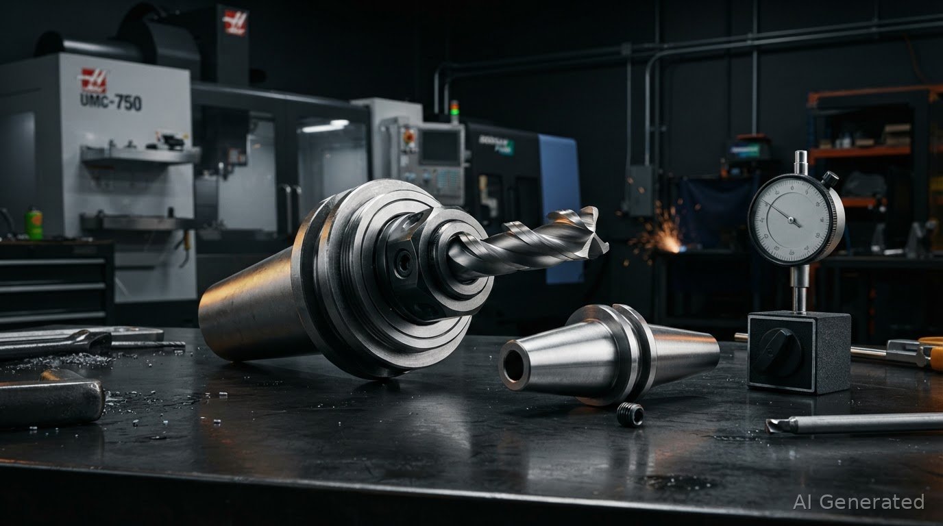
Friction grip alone cannot survive aggressive radial milling cuts. When heavy roughing cycles generate massive axial pull, standard friction collets invite tool slippage that ruins expensive workpieces and destroys solid carbide edges. Every machinist knows the cost of chasing severe chatter and dealing with inconsistent runout across automated tool stations. Solid end mill holders designed with positive mechanical locking deliver the uncompromising rigidity required to handle severe cutting loads.
You don't need to spend thousands on specialized shrink-fit machines to keep tools locked in place. By mastering holder geometry, taper specifications, and total indicated runout benchmarks, you can achieve predictable cutting performance and extended tool life on any machine tool. This guide covers how to select rigid tooling matched to cutting forces, hit repeatable 0.0002 to 0.0003 inch TIR, and dial in taper setups for absolute process reliability.
Key Takeaways
- Solid end mill holders provide positive mechanical locking against Weldon flats, stopping axial tool creep during high-load roughing cuts.
- Holding runout between 0.0002 and 0.0003 inch TIR protects carbide cutting edges and prevents premature chipping under severe chip loads.
- Selecting mechanical lock designs over standard friction collets eliminates cutter pull-out risks during aggressive radial passes.
- Certified G2.5 balancing at 30,000 RPM and precision AT3 taper grinding maintain spindle stability across high-speed cycles.
- Disciplined taper cleaning and calibrated set screw torque prevent bore damage, thread galling, and runout stacking.
Engineering Fundamentals of Industrial End Mill Holders
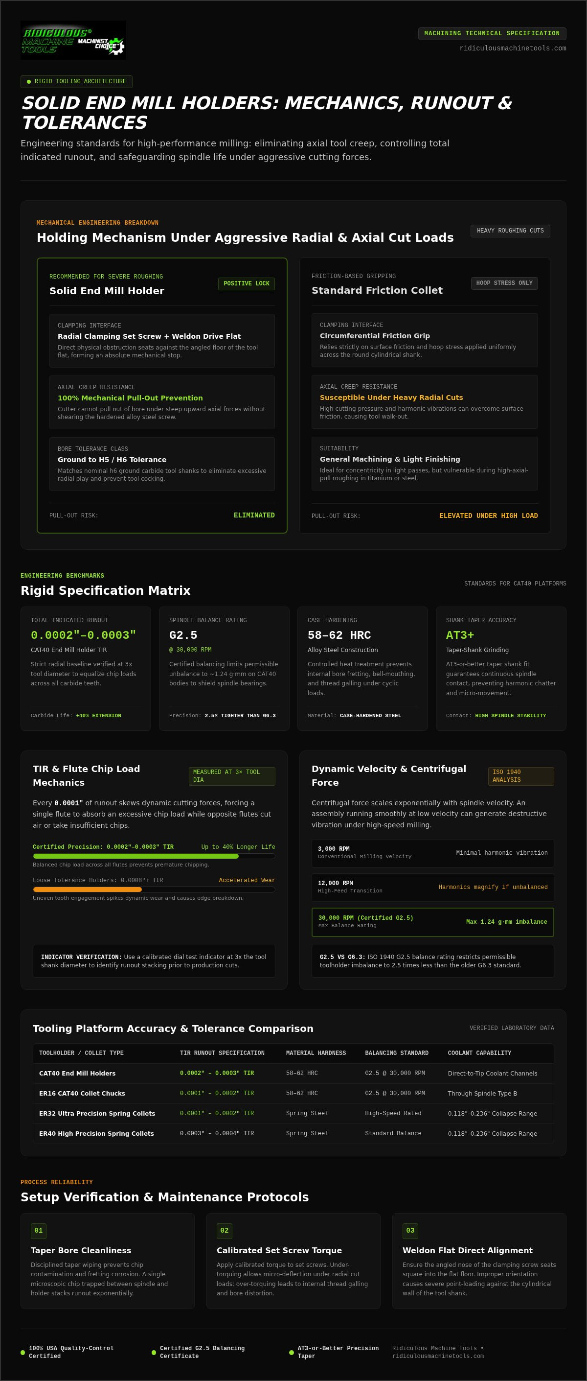
An industrial end mill holder functions as a rigid, dedicated mechanical lock assembly engineered to secure straight-shank cutting tools against extreme radial cutting loads. While general machining operations often rely on ER collet systems, aggressive roughing demands unyielding resistance to tool displacement. High-performance milling generates steep upward axial forces along the tool flutes. Friction-based gripping mechanisms rely strictly on hoop stress applied across the tool circumference. Under heavy cuts, vibration and cutting pressure can overcome that surface friction. Solid end mill holders solve this vulnerability through direct physical obstruction.
Modern tooling platforms incorporate precision internal coolant delivery paths alongside this locking mechanism. Direct-to-tip coolant channels route high-pressure fluid straight to the cutting zone. This pressurized stream blasts chips out of deep pockets, preventing recutting and catastrophic thermal shock when running high-temp alloys.
Weldon Flat Clamping Mechanics and Positive Locking
Positive locking relies on the interaction between a radial clamping set screw and the drive flat ground into the cutting tool shank. When machining steel or titanium, an end mill experiences continuous axial pull caused by the helix angle of the flutes. The clamping screw features an angled nose that seats firmly against the angled floor of the Weldon flat. This physical interlock creates a mechanical stop. The cutter cannot walk out of the bore without shearing the hardened steel screw. Proper alignment during setup ensures the flat faces the screw directly, preventing point-loading against the cylindrical wall of the shank.
Internal Bore Ground Tolerances and Fitment
Mechanical security depends heavily on precise cylindrical mating between the tool shank and holder bore. Quality holders undergo precision cylindrical grinding to maintain strict internal clearances:
- Target Fitment: Bore dimensions ground to an H5 or H6 tolerance class match nominal h6 ground carbide shanks, eliminating excessive side play.
- Deflection Control: Excessive bore clearance allows the tool to cock slightly under set screw pressure, multiplying runout and accelerating cutting edge breakdown.
- Radial Precision: Controlled internal tolerances establish a repeatable 0.0002 to 0.0003 inch TIR baseline, preventing premature tool wear during heavy industrial milling.
Total Indicated Runout, Balance Ratings, and Tool Life
Excessive runout destroys solid carbide before cutting edges ever reach their normal wear life. Many commodity toolholders treat concentricity as an afterthought, shipping with unground bores that cock tools off-center. In high-feed milling, dynamic balance and bore accuracy dictate whether a tool survives heavy radial engagement or chips out on the first pass.
TIR Benchmarks: 0.0002 to 0.0003 Inch Tolerances
Measuring runout at 3x tool diameter using a dial test indicator quickly exposes holder flaws. Every 0.0001 inch of runout forces one flute to take an oversized chip load, causing rapid abrasive wear and edge fracture. As demonstrated in high-speed spindle runout research, uneven cutter engagement spikes dynamic forces and accelerates tool failure. Maintaining a strict 0.0002 to 0.0003 inch TIR baseline distributes chip loads equally across all teeth, extending carbide life by up to 40% compared to sloppy commercial holders.
Spindle Dynamics and Certified G2.5 Balancing at 30,000 RPM
Centrifugal force scales exponentially with spindle velocity. An assembly that runs quietly at 3,000 RPM can generate severe destructive vibration at 12,000 RPM if not balanced correctly. Under ISO 1940 specifications, a G2.5 balance rating allows 2.5 times less unbalance than an obsolete G6.3 rating. On a standard CAT40 holder body, this tolerance restricts permissible imbalance to approximately 1.24 gram-millimeters. Certified dynamic balancing to G2.5 at 30,000 RPM prevents harmonic chatter and shields spindle bearings from premature failure. Running certified high-speed end mill holders ensures your spindle runs smooth through aggressive roughing cycles.
Material Hardness and Wear Resistance: 58-62 HRC
Heavy roughing generates punishing lateral deflection against the toolholder pocket. To withstand these cyclic forces, holders are forged from premium alloy steel and case hardened to 58-62 HRC. This controlled heat treatment delivers vital mechanical benefits:
- Bore Durability: Surface hardness stops the tool shank from fretting or bell-mouthing the internal bore under high radial pressure.
- Thread Integrity: Hardened internal threads prevent stripping and galling when tightening clamping set screws to full torque.
- Core Toughness: A ductile internal core absorbs heavy cutting shocks during interrupted milling passes, preventing catastrophic body fractures.
End Mill Holders vs. Collet Chucks and Hydraulic Holders
Every toolholding interface involves distinct mechanical trade-offs between runout, gripping power, and capital cost. While spring collets excel at finishing and hydraulic chucks damp vibrations, neither provides the absolute axial lock needed when hogging material. Standard friction chucks rely solely on circumferential clamping. When aggressive helix angles pull downward under heavy chip loads, friction fails and tools walk out. Dedicated end mill holders eliminate this failure mode by locking set screws directly against the cutter flat.
| Toolholding Type | Locking Mechanism | Typical Runout (TIR) | Pull-Out Risk | Relative Tooling Expense |
|---|---|---|---|---|
| Solid End Mill Holder | Mechanical Weldon set screw | 0.0002" – 0.0003" | Zero (positive physical lock) | Low (no external setup machinery) |
| ER Spring Collet Chuck | Frictional slotted steel taper | 0.0003" – 0.0006" | Moderate to high under heavy cuts | Low (flexible bore ranges) |
| Hydraulic Chuck | Internal fluid bladder pressure | ≤ 0.0001" – 0.00012" | Low to moderate on high-feed axial cuts | Moderate to high |
| Thermal Shrink-Fit | Direct interference thermal fit | ≤ 0.0001" | Low (requires dedicated heated unit) | High (requires capital induction heater) |
Thermal shrink systems provide high grip, but they demand induction heaters running thousands of dollars. Mechanical set screw holders achieve zero axial slip instantly with a standard hex wrench. Consult our tool holding solutions guide for broader machine setup frameworks across various spindle types.
Heavy Roughing and High Radial Load Operations
Full-slotting, ramping, and aggressive pocketing in 4140 steel, stainless, or titanium push cutting forces to extremes. High-helix cutters act like corkscrews, dragging the tool shank out of plain friction bores. Once a cutter slips even 0.010 inches downward, the next toolpath cuts too deep, gouging the part and destroying spindle tapers. Running production shifts without positive-locking end mill holders risks scrapping high-value components.
Balancing Grip Security and Finish Quality
Production workflows benefit from segregating roughing cycles from final profiling operations:
- Roughing Passes: Use set screw holders for heavy material removal where maximum chip evacuation and pull-out resistance take priority.
- Finishing Passes: Switch to precision ER spring collets or hydraulic chucks to take light radial cuts, utilizing 360-degree gripping to maximize surface finish.
Selecting Taper Standards and Bore Sizes for Production
Matching holder architecture to spindle capabilities determines process stability before the cutter ever touches material. Poor taper fitment destroys spindle health, creates chatter, and ruins bore concentricity under high chip loads. Systematic selection follows four straightforward steps:
- Step 1: Verify Spindle Interface: Confirm your machine uses CAT, BT, or HSK tapers. Match drive key slots and install machine-specific pull studs torqued precisely to manufacturer limits.
- Step 2: Match Tool Shank Dimensions: Match nominal bore diameter directly to the tool shank ground size. Never clamp undersized or metric shanks into standard inch bores.
- Step 3: Select Gage Length: Run the shortest projection possible. Extra overhang amplifies leverage and accelerates tool deflection.
- Step 4: Confirm Coolant Routing: Match through-spindle porting or DIN coolant channels directly to your machine delivery setup to flush chips efficiently.
CAT40 vs. CAT50 and AT3 Taper Shank Grinding
CAT40 tapers serve as the standard workhorse for 15 to 30 horsepower machines, handling cutters up to 1 inch for general production. CAT50 tapers provide massive flange contact and mass, making them necessary for heavy hogging in large titanium or nickel-alloy forgings on 50-taper mills. Regardless of taper size, ground accuracy matters. Precision end mill holders ground to AT3 taper tolerances guarantee at least 80% surface contact with the spindle socket. Substandard taper grinding leaves high spots, driving fretting corrosion and spindle bell-mouthing under aggressive side loads.
Gage Length Selection to Prevent Cutting Deflection
Tool deflection increases as a cubic function of overhang. Doubling holder projection multiplies deflection by a factor of eight under identical radial cutting forces. Keep gage lengths as compact as fixture access allows:
- Stubby Projections: Choose short gage lengths (1.75 to 2.50 inches) for deep slotting, plunging, and aggressive peripheral passes to maximize static rigidity.
- Extended Lengths: Reserve extended reach holders for clearing tall workholding, multi-axis trunnions, or deep cavity walls.
Lock down your milling setups today. Shop precision CAT40 end mill holders built with certified AT3 taper grinding to keep production running true.
Setup Verification, Maintenance Protocols, and Toolholder Selection
Rigorous shop floor maintenance protects precision tooling investments and prevents scrap. Even the best tooling assembly fails if mounted into a contaminated spindle or tightened with worn hardware. Establishing disciplined setup protocols ensures your milling operations maintain tight tolerances cycle after cycle.
Spindle Cleanliness and Set Screw Torque Verification
Contamination between the spindle socket and holder body creates immediate angular runout. A single 0.0005 inch chip trapped against the taper flange can displace the tool tip by several thousandths. Enforce these practical maintenance habits at the machine:
- Clean Interfaces Thoroughly: Wipe spindle tapers, holder shanks, and cutter flats with lint-free cloths and clean solvent before every tool change. Never insert oily, grimy tapers into dry spindles.
- Inspect Contact Surfaces: Check shanks regularly for fretting corrosion or scoring. Fretting marks indicate micro-movement caused by insufficient drawbar retention force.
- Torque Set Screws Accurately: Use calibrated torque wrenches rather than standard L-keys. Tightening a 5/8-18 set screw beyond manufacturer ratings deforms the internal bore, while under-torquing invites chatter.
- Swap Fatigued Screws: Replace clamping screws showing rounded hex sockets or burred nose profiles. Worn screw tips unevenly push the cutting shank, destroying bore concentricity.
Run regular runout audits across your automated tool magazines. Chuck a ground calibration arbor into active holders monthly and swing a 0.0001 inch dial test indicator. Any station showing drift beyond baseline tolerances requires immediate bore cleaning, screw replacement, or pull stud inspection.
Sourcing High-Tolerance Holders from Ridiculous Machine Tools
Eliminating process variability starts with predictable tooling hardware. Ridiculous Machine Tools supplies industrial facilities and CNC machine shops directly, cutting out distributor markups without cutting corners on precision. Every CAT40 end mill holder comes certified with 0.0002 to 0.0003 inch TIR runout precision, hardened to 58-62 HRC, and dynamically balanced to G2.5 at 30,000 RPM. Precision AT3-or-better taper grinding ensures maximum spindle contact area, keeping heavy roughing cuts completely stable. Equipping your machine carousels with factory-inspected end mill holders ensures consistent part finishes and dependable cutter retention across every production shift.
Lock Down Your Milling Setups for Maximum Rigidity
Eliminating tool slippage during aggressive roughing cycles comes down to mechanical fundamentals. Positive set screw engagement provides the physical lock required to stop axial creep under heavy chip loads, safeguarding valuable workpieces from catastrophic failure. Paired with strict concentricity controls, proper mechanical locking delivers predictable tool wear and uniform chip thickness across every cutting flute.
Ridiculous Machine Tools supplies machine shops directly across the country, cutting distributor markups without cutting corners on precision. Engineered with certified 0.0002 to 0.0003 inch TIR, certified G2.5 dynamic balancing verified at 30,000 RPM, hardened 58-62 HRC alloy steel construction, and precision ground AT3 tapers, this tooling eliminates harmonic chatter and preserves spindle bearing life.
Take the guesswork out of your roughing operations. Upgrade your machine shop with precision CAT40 end mill holders to lock down cycle stability and boost production throughput on every shift.
Frequently Asked Questions
Can you use an end mill without a Weldon flat in a set screw holder?
No, you should never clamp a plain cylindrical shank with a set screw. Tightening a hardened screw against a curved, hardened carbide surface creates extreme point loading that fractures the cutter or strips the screw threads. Plain cylindrical shanks slip immediately under heavy cutting torque. Use precision ER collets or hydraulic chucks for round shanks, and reserve solid end mill holders for Weldon flat tooling.
What causes an end mill to pull out of its holder during milling?
Upward axial cutting forces generated by right-hand tool spirals pull cutters downward during aggressive milling. High helix angles amplify this corkscrew effect under heavy chip loads. If you rely on friction alone, cutting chatter, improper tightening torque, or oily residue on mating shanks breaks the grip. The tool walks out axially, destroying depth accuracy, snapping the cutter, and scrapping the workpiece.
How does an end mill holder differ from an ER collet chuck?
End mill holders use a radial set screw to lock directly against a flat for positive mechanical retention. This design provides maximum resistance to tool pull-out during heavy roughing passes. ER collet chucks use a slotted, flexible spring steel sleeve that compresses 360 degrees around the shank via friction. Collets offer lower runout for precision finishing, while set screw holders deliver raw gripping security under punishing radial loads.
Why is certified G2.5 balancing necessary at 30,000 RPM?
Centrifugal force compounds exponentially as spindle speeds climb. An assembly running smoothly at 3,000 RPM can shake a spindle apart at 12,000 RPM or higher without proper dynamic balancing. A certified G2.5 balance rating restricts permissible imbalance to approximately 1.24 gram-millimeters on a CAT40 body. This balance level suppresses high-frequency harmonics, protects internal spindle bearings, and prevents chatter marks on finished surfaces.
What does an AT3 taper accuracy specification mean for a machine spindle?
AT3 is an internationally recognized taper tolerance standard defining the precision of the steep taper shank. A holder ground to AT3 tolerances ensures at least 80% direct surface contact with the spindle socket. Substandard taper grinding leaves high spots and air gaps. These gaps cause microscopic rocking under load, leading to fretting corrosion, high runout, and permanent bell-mouthing damage inside the machine spindle.
How tight should you torque the set screws on an end mill holder?
Always tighten clamping screws using a calibrated torque wrench to the exact manufacturer rating. For example, standard 5/8-18 set screws on 3/4-inch holders typically require 45 to 65 foot-pounds of torque depending on the thread class. Under-torquing allows the cutter to vibrate loose during interrupted cuts. Over-torquing deforms the internal ground bore, pinches the shank off-center, and introduces severe cutting runout.
Does a longer holder gage length increase cutting runout and chatter?
Yes, tool deflection increases drastically with longer holder projection. Deflection scales as a cubic function of length, meaning doubling the holder overhang multiplies deflection by eight under identical cutting forces. Extra overhang amplifies machining chatter, destroys surface finishes, and chips delicate carbide edges. Always select the shortest practical gage length that provides safe physical clearance around your workholding fixtures.