

Tap drill chart Best Practices and Expert Advice
Posted by RMT on Oct 23rd 2026
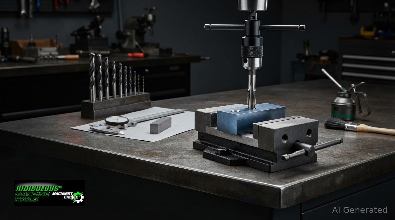
A tap drill chart helps you select a starting drill size for a thread, but the correct entry depends on the full thread designation, series, and measurement system. Use the steps below to read a chart, account for the tap and work material, and verify the hole and setup before tapping.
- Tap Drill Chart Basics: Match the Tap, Thread Series, and Drill
- Why a Tap Drill Chart Is a Starting Point, Not a Universal Answer
- How to Read a Tap Drill Chart and Select a Listed Drill
- From Tap Drill Chart to Tapped Hole: Verify the Setup
Key Takeaways
- Confirm the full thread designation, series, units, and drill notation before selecting a size from a tap drill chart.
- Check the drilled hole’s diameter, condition, depth, and alignment before tapping.
- For a blind hole, allow room for the drill point and tap lead as well as the required full-thread depth.
- Choose a tap holder that matches the tap’s shank and drive. An ER Tap Collet can hold compatible taps with the correct dimensions and square drive.
Tap Drill Chart Basics: Match the Tap, Thread Series, and Drill
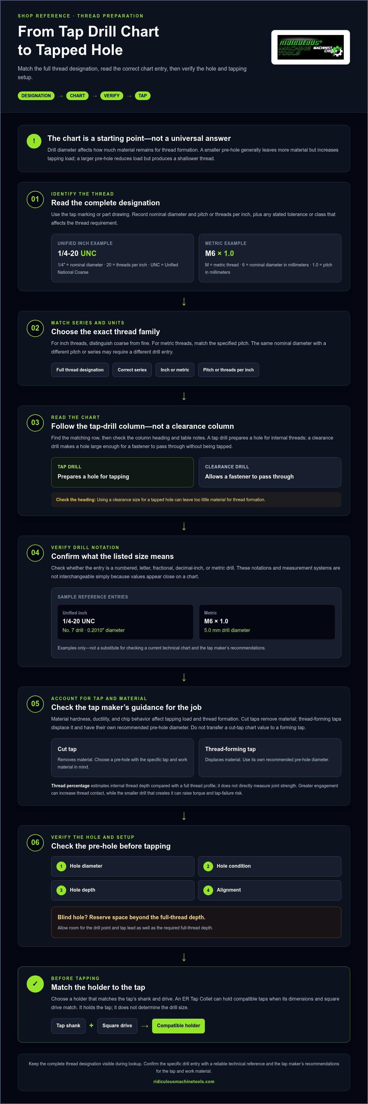
A tap drill chart pairs a thread designation with a starting drill size for preparing a hole to be tapped. Read the entire designation before choosing a row. Nominal diameter by itself is not enough: pitch or threads per inch, thread series, and measurement system all affect the applicable entry.
Read inch and metric thread designations correctly
In 1/4-20 UNC, 1/4" is the nominal diameter, 20 is the number of threads per inch, and UNC identifies the Unified National Coarse series. The same nominal diameter with a different thread count or series has a different pitch and may require a different drill size.
In M6 × 1.0, M identifies a metric thread, 6 is the nominal diameter in millimeters, and 1.0 is the pitch in millimeters. A fine-pitch metric thread has a different pitch from a coarse thread of the same nominal diameter. Keep inch and metric entries distinct. A drill number, fractional-inch size, decimal-inch size, and millimeter value are not interchangeable because they appear close on a chart.
A useful chart identifies the measurement system, complete thread designation, pitch or threads per inch, and tap drill size. Treat that as a checklist for reading a reference, not as a size recommendation. Verify a specific drill value against a reliable technical reference and the tap maker’s guidance before using it.
Tell tap drills apart from clearance drills
A tap drill prepares a hole for internal threads. A clearance drill makes a hole large enough for a fastener to pass through without being tapped. These are separate operations, so check the column heading and table notes to confirm which size is listed. The Drill and tap size chart separates tap and clearance information alongside inch and metric references. Using a clearance size for a tapped hole can leave too little material for thread formation.
Why a Tap Drill Chart Is a Starting Point, Not a Universal Answer
The drill diameter determines how much material remains for the tap to cut or displace. A smaller pre-hole generally leaves more material for thread formation, but increases tapping load. A larger hole reduces the load but produces a shallower thread. Use the chart as a starting point, then account for the tap type, work material, hole geometry, and thread requirements.
How material and tap type affect the choice
Material hardness, ductility, and chip behavior affect tapping load and thread formation. A pre-hole that works in one material may not suit another. Tap type matters as well: cut taps remove material, while thread-forming taps displace it. Forming taps have their own recommended pre-hole diameter, so do not transfer a cut-tap chart value to a forming tap. Follow the tap maker’s recommendations for the specific tap and material.
What thread percentage tells the machinist
Thread percentage estimates the internal thread depth compared with a full thread profile. It can help compare how much of the nominal thread form the hole supports, but it does not directly measure joint strength. Greater engagement can increase thread contact. The smaller drill that creates it can also raise torque and the risk of tap failure, so more engagement is not automatically better.
Consider the material, tapped-hole length, through or blind-hole geometry, fastener loads, and the tap maker’s recommendations together. A through-hole in a machinable alloy and a blind hole in a tougher material may call for different process choices. Reference tables such as Engineers Edge’s Tap and Drill Size Charts can help compare thread systems and tap types, but use the guidance that matches the tap and work material. Once the pre-hole is established, choose a compatible holder. An ER Tap Collet holds compatible taps with a matching shank and square drive; it does not determine the drill size.
How to Read a Tap Drill Chart and Select a Listed Drill
Use the same lookup sequence for a shop chart, printed reference, or digital table. A tap drill chart is useful only when the thread designation, series, and units match the tap and job documentation. Keep the full designation visible while looking it up so a partial match on nominal diameter does not lead to the wrong row.
- Identify the thread. Read the tap marking or part drawing. Note the nominal diameter and pitch or threads per inch, along with any stated tolerance or class that affects the thread requirement.
- Choose the series. Select the exact thread family in the designation. For inch threads, distinguish coarse from fine. For metric threads, match the specified pitch rather than using the nominal diameter alone.
- Find the tap-drill entry. Follow the matching row to the column labeled for tapping or tap drill. Read the column heading and table notes before selecting the value.
- Verify notation and units. Confirm whether the entry is a numbered, letter, fractional, decimal-inch, or metric drill. Check that it is not a clearance size or a value shown in another unit.
Sample reference entries
- Unified inch: 1/4-20 UNC, drill No. 7, 0.2010" diameter.
- Metric: M6 × 1.0, 5.0 mm drill diameter.
These examples show how chart entries may be written, not a substitute for checking a reference. Confirm each entry against a current technical chart and the tap maker’s recommendations, especially if the tap type or material calls for a different pre-hole. If the tap marking is incomplete or illegible, resolve the thread designation from the drawing or job documentation before choosing a drill.
If the listed drill is unavailable, compare actual diameters in a reliable drill-size reference or measure the candidate drill. Do not choose by label or appearance alone. Compare its diameter with the listed size and consider the effect on the pre-hole and thread requirement. Record the selected drill and its measured or published size on the setup sheet to make repeat runs and tool replacement easier to manage.
From Tap Drill Chart to Tapped Hole: Verify the Setup
After confirming the drill size, check the hole and tapping setup. A correct chart entry cannot compensate for a damaged drill, insufficient hole depth, misalignment, or chips obstructing the tap.
Check depth and alignment before tapping
Inspect the drill for damage and confirm its diameter. In a blind hole, distinguish the required full-thread depth from the drilled depth. The drill point leaves a tapered bottom, and the tap lead has incomplete cutting threads before the full-profile threads engage. The hole must provide room for the drill point and tap lead in addition to the required full-thread depth. Use the drill and tap makers’ guidance for the actual point geometry and tap design instead of adding an assumed allowance.
Keep the tap axis aligned with the hole as it enters. A misaligned start can produce crossed or uneven threads and increase load on the tap. Choose an alignment method appropriate to the machine and operation, and follow the tap maker’s recommendations for lubrication and chip evacuation. For blind holes, manage chips so they do not collect at the bottom and obstruct the tap’s travel.
Match the tap holder to the tap
Choose the holder after confirming the pre-hole size and thread. Ridiculous Machine Tools offers ER Tap Collets for compatible ANSI-style taps. Check the tap dimensions and applicable tooling specifications before choosing a collet, since compatibility depends on the tap and holder.
Tap holding is the final compatibility decision. It does not replace selecting and verifying the correct drill.
Carry a Verified Tapping Setup Into the Next Job
Make the selected tap and drill part of a repeatable shop-floor setup. Record the thread designation, pre-hole diameter, tap type, material, and hole depth with the job documentation. This gives the next operator a clear reference and makes the process easier to review if a tap binds, a thread fails inspection, or the application changes.
A tap drill chart is a reference, not a substitute for applying the entry to the actual workpiece and tapping method. Keep the lookup tied to the part requirements, then select compatible tooling for the operation. Ridiculous Machine Tools supplies precision machine-tool accessories and CNC tooling, including ER Tap Collets for compatible applications.
For the next tapping setup, verify the thread, pre-hole, depth, alignment, and tap-holder compatibility before machining.
Frequently Asked Questions
What drill depth should I use for a blind tapped hole?
Drill beyond the required full-thread length to account for the tap lead and drill-point taper. The allowance depends on the drill geometry and tap design, so use their manufacturers’ guidance rather than relying on the tap drill chart alone. Account for chip space when the tapping method requires it, and verify the depth plan and tool path before machining.
Can I use a fractional drill when a chart lists a number or letter size?
Yes, if its measured or published diameter suits the application. Compare the fractional drill’s diameter with the listed size and consider how the difference affects the pre-hole and resulting thread. Do not choose based only on how close the labels appear. Follow the drawing or process documentation for specified thread requirements, and record the selected size for repeat setups.
Does a tap drill chart tell me the tapping speed?
Usually not. A tap drill chart lists pre-hole diameters. Tapping speed and cutting conditions depend on the work material, tap geometry, machine control, and coolant or lubrication requirements. Follow the tap maker’s recommendations for the tap and material. Include blind-hole geometry and chip-control needs in the setup review rather than treating drill size as the only variable.
Can I use the same pre-hole size for a cut tap and a thread-forming tap?
Do not assume so. A cut tap removes material, while a thread-forming tap displaces it, so their recommended pre-hole diameters can differ for the same thread designation. When changing tap types in a production process, check the tap maker’s size and material recommendations again. Verify the hole size before updating a program or setup sheet.

Article by
Ridiculous Machine Tools Technical Team
The Ridiculous Machine Tools Technical Team provides practical information about precision machine tooling, CNC tooling, workholding, and related manufacturing applications. RMT focuses on helping machinists, manufacturers, fabricators, and other customers understand tooling specifications, compatibility, selection, and proper application. Our technical content draws on product specifications, industry knowledge, and RMT's quality-control experience to provide clear, useful information for selecting and using machine tooling and workholding products.
Ridiculous Machine Tools — Machinist's Choice™