

Stop Chip Packing in Collets to Cut Runout
Posted by RMT on Oct 28th 2026
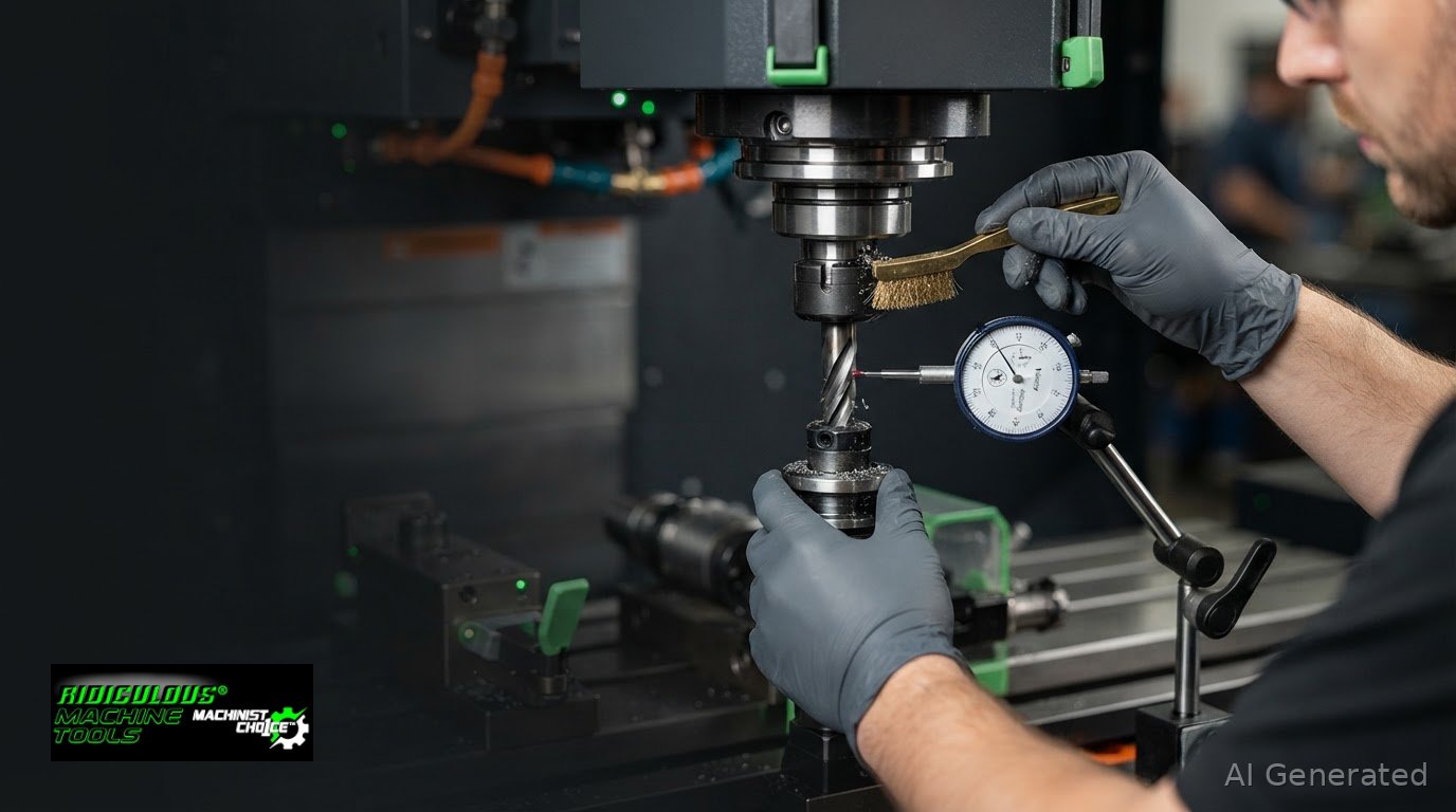
Chip packing inside collet slits can lead to tool runout, so clear debris and inspect the collet, nut, holder, and spindle contact surfaces before changing the cutting tool; for solid round tools, a practical T.I.R. target is 0.0002" or less. Runout can load cutting edges unevenly, affecting tool wear and finish, while damage or wear elsewhere in the toolholding system may remain after cleaning. This article covers chip removal, component inspection, indicator measurements, and how to compare high-precision toolholder specifications with your machine interface and application requirements.
Key Takeaways
- Clear chips from the collet slits and mating surfaces before reinstalling the tool; debris can interfere with even clamping.
- Inspect the collet, nut, and holder for wear, galling, or fretting so damaged components don’t get mistaken for a cutting-tool problem.
- Use an indicator to isolate runout at the spindle, holder, and tool rather than relying on a single reading.
- Compare ER collets by compatible series and published T.I.R. specifications to match the toolholding setup to the job’s accuracy demands.
Chip evacuation using peck drilling or through-spindle coolant
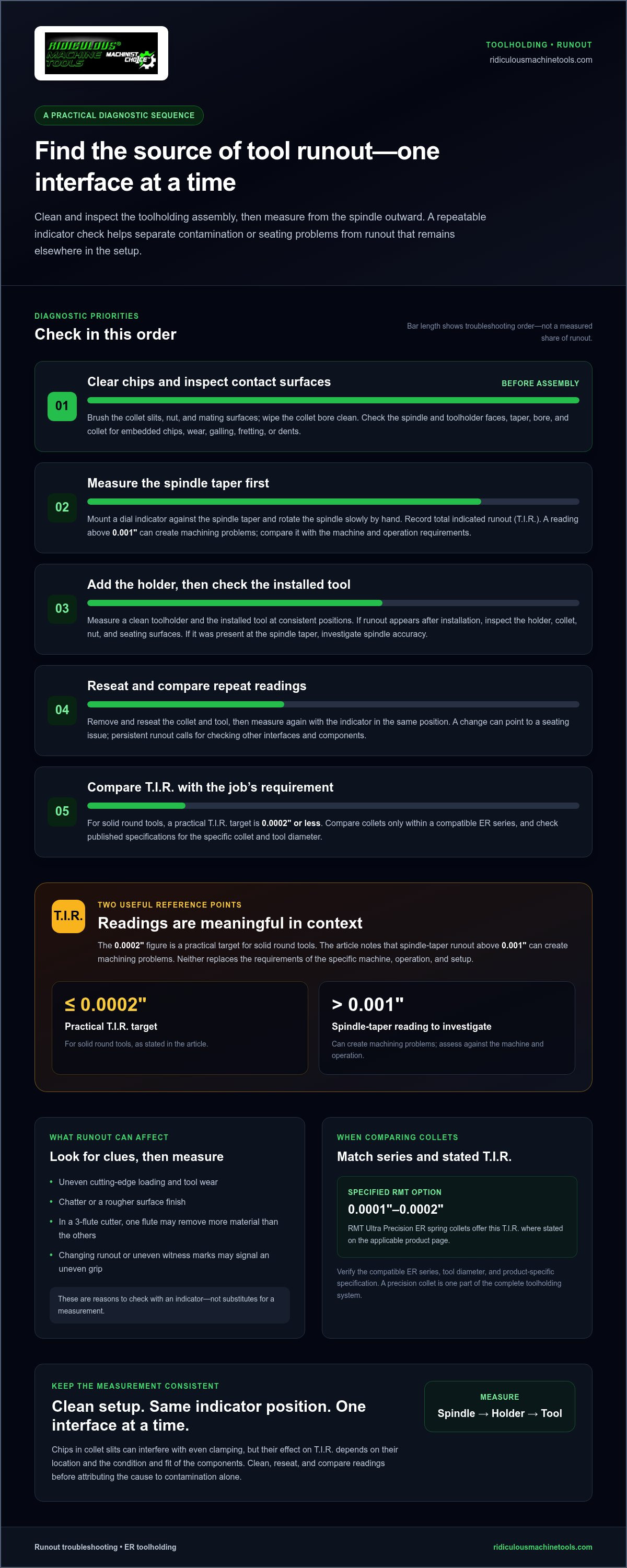
Before assembly, remove chips from the collet slits, nut, and spindle taper with a soft brush and clean cloth, then inspect the surfaces. Excessive runout can load cutting edges unevenly, damage tools, degrade the finish, distort workpiece features, and contribute to spindle-bearing wear.
- Clear chips during drilling. Use peck drilling or through-spindle coolant to evacuate chips from the hole and reduce recutting. Packed chips can push a drill off center, creating uneven cutting forces or oval holes. For deep drilling, high-pressure coolant systems at 1000+ PSI can help move chips out.
- Clean the collet assembly. Remove the ER spring collet and nut, then brush debris from each slit and contact surface. Wipe the collet bore and nut clean before reassembly. Chips trapped in slits can prevent even clamping, so inspect each slot under good lighting.
- Check the mating faces. Remove dust and debris from the spindle face and toolholder face before seating the holder. On an HSK63F setup, particles between these faces can contribute to runout. Keep the contact surfaces clean and dry, then seat the holder fully.
- Measure spindle-taper runout. Mount a dial indicator against the spindle taper and rotate the spindle slowly by hand. Watch for needle movement and record the total indicated runout. A reading above 0.001 inches can create machining problems; compare measurements with the machine and operation requirements.
- Separate spindle and toolholder error. Check the spindle taper first, then measure a clean toolholder and installed tool at consistent positions. If taper runout appears before the holder is installed, investigate spindle accuracy. If it appears after installation, inspect the holder, collet, nut, and seating surfaces. For compatible options, compare ER spring collets by their stated T.I.R. specifications.
Collet chuck and toolholder condition
Inspect the collet assembly before changing cutting parameters. Use these steps to identify contamination, wear, or incorrect assembly.
-
Inspect Collet Chuck and Toolholder
Remove the toolholder from the spindle and examine its taper, bore, and contact surfaces under good lighting. Check the ER collet, nut, and chuck for visible wear, galling, fretting, dents, or embedded chips. Damage can prevent even contact and affect clamping. Do not use questionable components in a cutting setup until you have assessed their condition.
-
Identify Chip Contamination Symptoms
Look for packed debris in the collet slits, uneven witness marks on the tool shank, or chips inside the bore. During cutting, contamination may appear as changing runout, chatter, inconsistent surface finish, or faster wear on one flute. These signs can indicate an uneven grip, but inspect the full assembly before blaming chips alone.
- Install the ER collet and nut correctly. With the spindle stopped, engage the collet in the nut’s eccentric ring before threading the assembly onto the chuck. Insert a clean tool shank within the collet’s collapsible range, then tighten with the correct wrench. Use the torque specified for that collet and chuck system; do not substitute a guessed value. A compatible ER collet chuck must match the collet series.
- Measure after assembly. Place a dial indicator against the tool shank and rotate the spindle by hand to observe T.I.R. Repeat the measurement after reseating the collet and tool. If the readings change, compare the nut, collet, shank, and holder individually. Repeatable measurements help distinguish a seating problem from visible component damage.
Radial runout and total indicated runout (T.I.R.)
Measure radial runout at the tool shank with a dial indicator, then compare the reading with cutting behavior. Debris has no fixed runout value: its effect depends on where it sits and how it disrupts collet contact.
-
Check Radial Runout and T.I.R.
Mount a dial indicator against the clean tool shank, then rotate the spindle slowly by hand. Record the full indicator movement as T.I.R., and keep the indicator position consistent between checks. For solid round tools, a practical target is 0.0002" or less. Radial runout shifts the tool’s rotation from its intended axis, changing how its cutting edges engage.
-
Assess Debris-Related Collet Runout
Before attributing a runout value to contamination, remove the tool and inspect the collet contact surfaces for trapped chips. A chip between the collet and shank can disrupt even clamping, but the resulting T.I.R. depends on the chip’s position, collet condition, and tool fit. Clean and reseat the assembly, then measure again. The change can help show whether contamination contributed.
- Compare cutting-edge contact. Watch for uneven wear after a test cut. In a 3-flute cutter, runout can make one flute remove more material than the others, causing uneven edge loading. That imbalance can contribute to premature chipping, chatter, or a rougher finish. Treat those signs as reasons to measure, not as a substitute for an indicator reading.
- Separate the tool from the holder. Measure the tool shank, then check the holder’s internal bore with a suitable test bar. Keep the setup and indicator position consistent for each reading. If tool runout changes after reseating, inspect the collet and contact surfaces again. If the readings persist, investigate other interfaces rather than assuming debris is the only cause.
- Match the collet to the tolerance target. Compare published T.I.R. specifications for the compatible collet series and tool diameter. For example, specified RMT Ultra Precision ER spring collets offer 0.0001"-0.0002" T.I.R. where stated on the applicable product page. Review ER spring collet options against the accuracy demands of your operation.
Runout and high-precision tool holders
Choose a high-precision holder by matching its interface and published specifications to the complete setup. A precision component is only one part of the system, so consider the machine connection, collet series, tool shank, and operating conditions together.
- Confirm the complete interface. Match the holder taper to the spindle and the collet series to the ER collet chuck. Then verify that the tool shank falls within the selected collet’s collapsible range. A mismatch at any connection can prevent proper seating or gripping, regardless of the component’s precision category.
- Compare the right specifications. Read the product-specific T.I.R. and determine what surfaces the stated measurement covers. Taper-to-bore runout describes the holder’s taper-to-bore relationship; it is not the same as a measurement of the installed tool. Keep those specifications distinct when comparing components.
- Choose for the operation. Consider tool diameter, stickout, cutting load, and required finish when selecting a toolholding setup. For a short-reach finishing pass, prioritize verified runout specifications and correct fit. For a heavier cut, also account for tool retention and setup rigidity rather than selecting by a precision label alone.
- Review coolant needs separately. If the process uses coolant-through delivery, select a compatible configuration. Steel Sealed ER Spring Collets are designed for coolant-through applications. Their pressure ratings and other specifications depend on the applicable product, so use those details when matching the collet to the machine and process.
- Compare measured results with the product data. Measure the assembled tool at a consistent position, then compare the reading with specifications for the exact components in use. The ER spring collet selection includes different precision levels and configurations, so select by verified product details and application fit.
Ridiculous Machine Tools: Horizontal Toggle Clamps
Ridiculous Machine Tools supplies Horizontal Toggle Clamps to secure workpieces in fixtures and machining setups. Stable workholding helps prevent movement during cutting, but a toggle clamp will not correct runout caused by a collet, spindle, or toolholder. Check workholding stability and toolholding accuracy separately.
Choose a horizontal hold-down design when its low-profile handle suits fixture clearance and operator access. For other fixture layouts, Ridiculous Machine Tools also offers Latch Toggle Clamps, Vertical Toggle Clamps, and Push-Pull Straight Line Toggle Clamps. Match the clamp style to how the fixture must hold or position the workpiece.
Visit Ridiculous Machine Tools to review Horizontal Toggle Clamps.
Build a Repeatable Tooling Check
Turn troubleshooting into a decision rule for each critical operation. Set acceptance criteria using the part tolerance, tool requirements, and published specifications for the assembled tooling. Document the measurement location and method so operators can compare setups consistently instead of changing cutting parameters without a clear diagnosis.
If chip packing inside collet slits is leading to tool runout, record what prompts inspection, which components you examine, and what corrective action you take. Make the criteria specific to the operation. Finishing and roughing may place different demands on the setup, so one acceptance threshold may not suit both.
Use these requirements to guide future tooling selection. First identify the machine interface, collet series, tool shank, and application demands. Then compare specifications for the exact configuration. Ridiculous Machine Tools offers tooling options to consider when selecting components for a machining setup.
A clear process gives your team a practical basis for its next setup decision.
Frequently Asked Questions
How Do You Minimize Runout?
To minimize runout, isolate its source before changing cutting settings. Check the spindle, toolholder, collet, nut, and tool shank as separate interfaces, using the same indicator position for comparison. If runout remains after cleaning and reseating, test another compatible collet or holder. This helps show whether the variation follows a component or remains with the machine setup.
Should I Modify My Tool?
Don’t modify the tool shank to compensate for runout. Grinding, polishing, or altering the gripping surface can affect fit and make the tool unsuitable for its holder. Instead, inspect for burrs or damage, confirm that the shank fits the collet’s specified range, and test a known-good tool. If the problem follows one tool, replace it with a compatible, undamaged tool.
What About Total Indicated Runout (TIR)?
T.I.R. is the full range of indicator movement as the measured surface rotates, from its highest reading to its lowest. For example, if the indicator swings between two dial positions, the difference is a single T.I.R. value. Record the measurement location and setup with each reading. T.I.R. describes the assembled measurement, not the cause of the variation.
What Can You Do About It?
Start by documenting where runout appears and whether it changes after reseating components. If the reading follows a particular collet, holder, or tool, inspect that part for wear or damage and replace it if needed. If readings persist with compatible tooling, compare measurements at the spindle interface. Keep notes by machine and setup to make recurring patterns easier to identify.
How do chips pack inside collet slits and cause tool runout?
Chips can enter the open slits during tool changes or machining and lodge between the collet fingers. When the nut tightens, the debris can interfere with the collet’s movement or contact with the tool shank. Chip packing inside collet slits leading to tool runout is more likely when readings change after disassembly, cleaning, and reseating.
How to measure tool runout at the collet and tool shank?
Secure a dial indicator on a rigid base, with its tip against a smooth cylindrical surface rather than a flute. Rotate the spindle slowly by hand and record the highest and lowest readings. Measure the shank near the collet and farther along the exposed tool, keeping the indicator aligned consistently. A changed reading farther from the collet may reflect a different setup or tool condition than the first measurement.

Article by
Ridiculous Machine Tools Technical Team
The Ridiculous Machine Tools Technical Team provides practical information about precision machine tooling, CNC tooling, workholding, and related manufacturing applications. RMT focuses on helping machinists, manufacturers, fabricators, and other customers understand tooling specifications, compatibility, selection, and proper application. Our technical content draws on product specifications, industry knowledge, and RMT's quality-control experience to provide clear, useful information for selecting and using machine tooling and workholding products.
Ridiculous Machine Tools — Machinist's Choice™