

Measuring Spindle Taper vs Tool Holder Runout
Posted by RMT on Nov 1st 2026
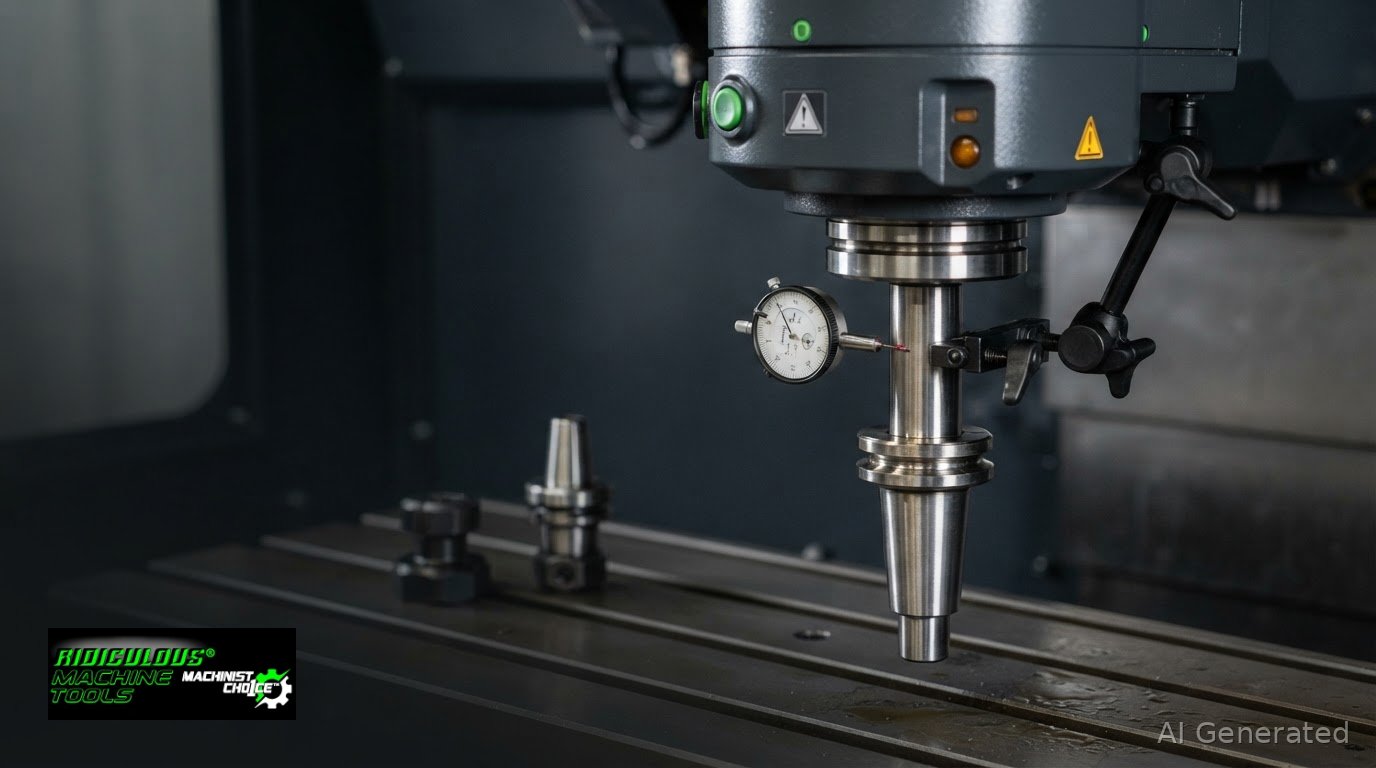
A tool-tip runout reading alone cannot show whether the spindle, toolholder, or the fit between them is causing the error. Measuring spindle taper runout versus tool-holder arbor runout helps isolate the source: indicate the spindle taper directly, then install a test arbor or toolholder and measure its runout. Keep the setup and indicator position consistent.
It is easy to blame the spindle when a cutting tool runs out, but each interface can contribute to the final reading. This article explains spindle runout, how to measure the spindle taper and an installed holder, and how to compare the results to trace the error. It also covers how readings can differ along the arbor and what to inspect if they change after cleaning or reseating the assembly.
Key Takeaways
- Indicate the spindle taper directly, then measure an installed test arbor or holder to separate spindle contribution from holder-related runout.
- Compare readings at multiple distances from the spindle face; a reading that grows farther along the arbor can reveal angular error or seating issues.
- Rotate and reseat the test arbor to help distinguish repeatable spindle runout from contamination or taper damage.
- Judge runout against the cutting operation: tool-tip readings of 0.0002-0.0005" are typical targets for many precision machining applications.
What Is Spindle Runout?
- Define the reading before diagnosing the machine. Runout is the variation of a rotating surface or tool from its intended axis. A dial indicator records total indicated runout, or T.I.R., as the spindle or assembly turns. The reading may reflect the spindle taper, arbor, holder, collet, or cutting tool. Treat it as an assembly measurement until you isolate each interface. A 0.0005" reading at the tool tip does not, by itself, identify which component caused the variation.
- Relate runout to flute loading. Runout shifts the cutting edge away from the rotation axis, so flutes may not share the cut evenly. In one example, 0.0005" of tool-tip runout on a four-flute end mill makes one flute do most of the cutting. If a toolholder has 0.003" runout and the end mill is rated for 0.004" chip load, only 0.001" remains available as intended chip load. The overloaded edge wears faster and can shorten tool life.
- Compare runout with the programmed chip load. A rule of thumb flags T.I.R. above about 20% of targeted chip load as a point where tool life declines sharply. For a 3/8" end mill, 0.0008" runout equals 29% of a 0.0028" chip load. For a 1/8" end mill, a 0.0006" chip load is less than the same 0.0008" runout. These examples show why a reading that seems small can matter more on a smaller cutter.
- Check drilled-hole size and form. Radial runout makes a drill rotate around an offset axis, sweeping a larger path than its nominal diameter. The stated example associates 0.001" radial runout with drilled-hole diameter variation of ±0.002" from nominal. Flexible drills or work-hardening materials may amplify bore errors by 1.5-2 times. Measure the finished bore for size and roundness; a single spindle reading cannot show the full effect of tool, material, and cutting conditions.
Troubleshooting spindle versus holder runout
Before measuring, stop the machine and clean the spindle taper and holder contact surfaces. Use a clean, lint-free cloth to remove chips, lint, and oil, then inspect both surfaces for burrs, dents, or embedded debris. Even a small contaminant can prevent full seating and distort a precision reading.
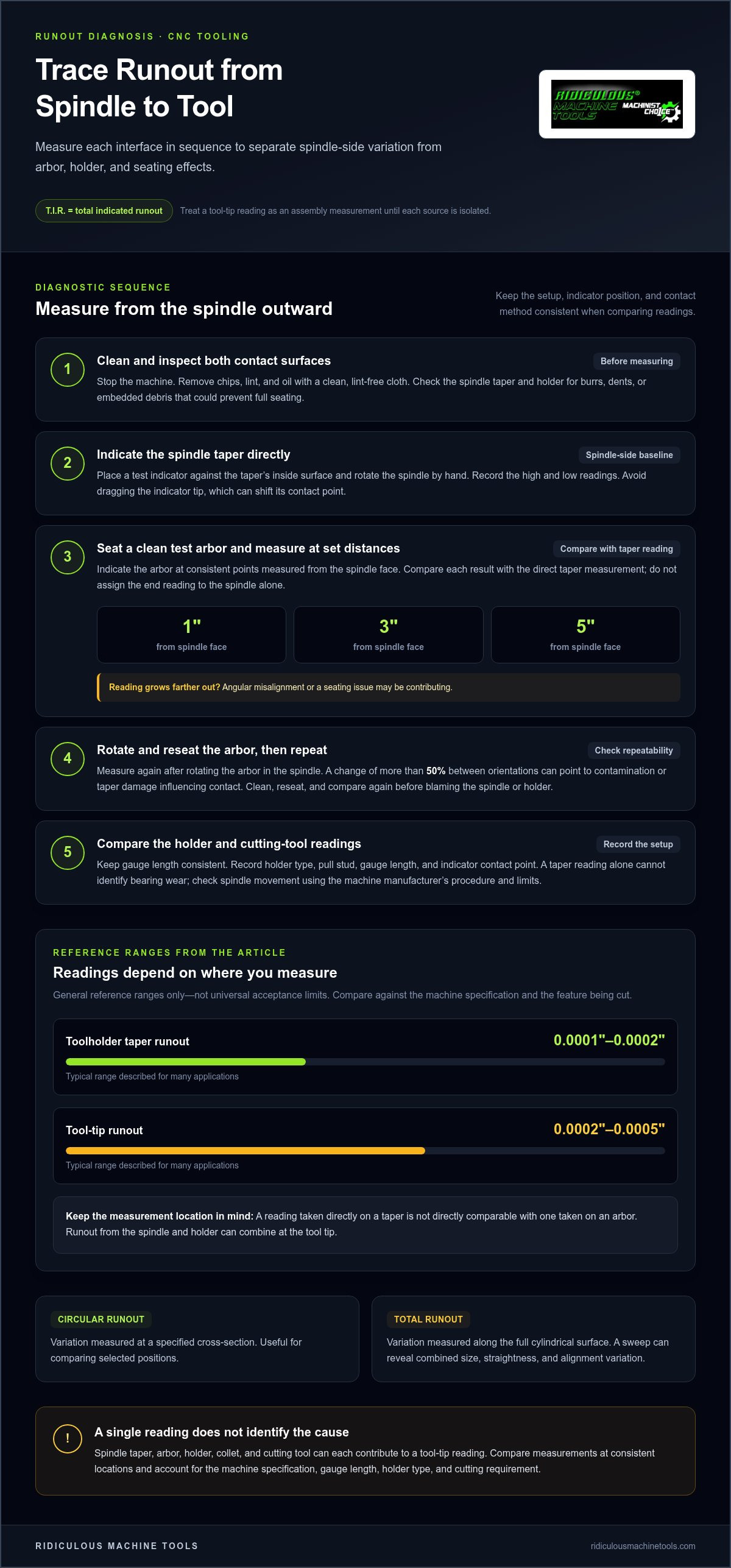
- Indicate the spindle taper directly. Position a test indicator against the taper’s inside surface and rotate the spindle by hand. Record the high and low readings. This isolates spindle-side variation before the holder enters the setup. Avoid dragging the indicator tip across the taper, which can shift its contact point.
- Measure the installed arbor at consistent locations. Seat a clean test arbor, then indicate it at 1", 3", and 5" from the spindle face. A larger reading farther out can point to angular misalignment or seating error. Compare each location with the direct taper reading rather than treating the end reading as spindle runout alone.
- Separate circular and total runout. Circular runout measures variation at a specified cross-section. Total runout measures variation along the full cylindrical surface. Use circular readings to compare selected positions; use a sweep along the arbor to reveal combined size, straightness, and alignment variation.
- Consider the cutting tool and material. Uneven flute loading can damage carbide edges through chipping, while HSS can tolerate more edge deflection before failure. A drilling example recorded 2,300 holes at 0.00008" runout versus 800 holes at 0.0006" with an HSS drill. That result shows why runout matters, not a universal tool-life prediction.
- Repeat the test after reseating. Rotate the arbor in the spindle and measure again. If the reading changes by more than 50% between orientations, contamination or taper damage may be influencing contact. Clean both interfaces again, reseat the arbor, and compare the new readings before blaming the spindle or holder.
Comparing spindle, test-arbor, and tool-holder runout
Compare readings from the spindle interface outward. This helps separate variation measured at the spindle taper, test arbor, holder, and tool.
-
Separate Bearing, Taper, and Holder Runout
Indicate the spindle taper directly, then compare that reading with a test arbor and installed holder. Hand rotation reveals repeatable surface variation, but it does not independently establish bearing condition. To investigate bearing movement, check radial or axial spindle movement under controlled force and compare the results with the machine manufacturer’s procedure and limits. A taper reading alone cannot diagnose bearing wear.
-
Evaluate Acceptable Runout Values
Compare each result with the machine specification and the feature being cut. Typical toolholder taper runout for many applications is 0.0001-0.0002", while typical tool-tip runout is 0.0002-0.0005". These are general reference ranges, not universal acceptance limits. Spindle and holder runout can combine, so consider their total before judging the result. Consider the cutting requirement before judging the result.
-
Account for Holder Type, Gauge Length, and Pull Stud
Keep gauge length consistent, since angular error can produce a larger reading farther from the spindle face. Holder design also matters: set-screw holders and Jacobs chucks typically show more runout than ER collets. A worn or poorly toleranced pull stud can affect seating. For useful comparisons, record the holder type, gauge length, pull stud, and indicator contact point alongside readings for the spindle taper and arbor.
What runout values are acceptable for a CNC machine spindle and tool holder?
- Begin with the machine specification. Compare the spindle’s measured runout with the machine manufacturer’s limit, using the specified indicator location and measurement method. A reading taken directly on a taper surface cannot be compared directly with one taken on an arbor. Also distinguish radial from axial readings; typical axial runout specifications are 0.0001-0.0003" TIR, but that range is not a universal spindle acceptance limit.
- Set a target for the holder and cutting operation. Typical toolholder taper runout for many applications is 0.0001-0.0002", and typical tool-tip runout is 0.0002-0.0005". Use these as general references, not guaranteed results or limits for every machine. The appropriate target depends on the cutter, tool stickout, operation, and part requirements. A finishing pass with a small cutter calls for closer scrutiny than a roughing cut.
- Check whether the part tolerance leaves enough margin. Features with tolerances tighter than four times the measured spindle runout can be challenging to produce consistently. Compare the specified part tolerance with the measured runout, then consider other contributors such as tool deflection, workholding movement, and cutting forces. This comparison identifies a potential risk, but does not predict the finished dimension on its own.
- Use a repeatable maintenance decision. Spindle runout exceeding 0.001" indicates maintenance is required. Before acting, repeat the measurement with clean, seated tooling and consistent indicator contact. Record the location, holder, gauge length, and whether the machine is cold or warmed up. Comparing those conditions helps distinguish a persistent change from setup variation and gives the shop a useful baseline for future checks.
Compare end mill holder specifications
Ridiculous Machine Tools: Horizontal Toggle Clamps
Runout troubleshooting requires measuring and comparing the spindle and tooling components. Horizontal Toggle Clamps serve a separate workholding function: they secure a workpiece or fixture rather than measure runout. Ridiculous Machine Tools also offers Latch Toggle Clamps and Vertical Toggle Clamps for manual workholding setups.
If your next shop-floor need is fixture clamping, choose a clamp style suited to the workpiece and the access required. Visit ridiculousmachinetools.com to explore Ridiculous Machine Tools’ toggle clamp options.
Put the Next Setup on a Sound Footing
Use runout readings to make a clear tooling decision, and apply the same measurement discipline to the next setup. Record spindle taper runout separately from tool-holder arbor runout so future checks compare like with like. In a machining cell, secure workholding and spindle accuracy address different problems, but both matter to process control.
Ridiculous Machine Tools offers Horizontal Toggle Clamps, Latch Toggle Clamps, and Vertical Toggle Clamps for fixtures that need manual workholding. Choose a clamp configuration based on how the workpiece must be held and accessed. A stable fixture provides a consistent base for cutting, while careful runout checks help assess the rotating tooling assembly.
Take the next step with a workholding option suited to your setup, or get in touch with Ridiculous Machine Tools.
Improve the setup one measured decision at a time.
Frequently Asked Questions
What is Runout in Machining?
Runout is measurable variation between a rotating surface and its intended axis. In machining, it can come from the spindle, toolholder, collet, arbor, or cutting tool. For example, if an indicator reading changes as a mounted arbor turns, the assembly is not rotating concentrically at the contact point. Identify which interface contributes before changing offsets or adjusting the cutting program.
How do you measure spindle taper runout with a dial indicator?
Secure an indicator to a stable part of the machine, position its tip against the spindle taper, and rotate the spindle by hand. Keep the contact point fixed and record the full high-to-low movement. Repeat the sweep to confirm the reading returns consistently. A shifting contact point or loose indicator stand can produce misleading measurements, so stabilize both before comparing results.
How do you measure tool holder arbor runout?
Seat the clean holder in the spindle, then place the indicator against a precision-ground arbor or test bar held by the assembly. Rotate the spindle by hand and record the indicator’s full movement. Keep the contact point and gauge length consistent when comparing results. If the holder uses an ER collet chuck, testing the bore without a collet helps separate holder runout from collet and tool contributions.
What is the difference between spindle taper runout and tool holder runout?
Spindle taper runout is the variation measured directly on the spindle’s taper surface. Toolholder runout is measured on the installed holder, arbor, or tool, so it includes the spindle-holder fit and the components being measured beyond it. A low taper reading paired with a higher arbor reading points attention toward seating, holder geometry, or the arbor itself.
Where should you place the indicator when measuring spindle taper runout?
Place the indicator tip on the taper’s contact surface, not on a nonfunctional face or unrelated cylindrical feature. Hold the tip steadily against the surface while turning the spindle by hand. Because the spindle taper’s angle affects how the tip meets the surface, maintain consistent contact throughout the sweep. Record the exact contact location so later checks can be compared.
What tools and indicator resolution are needed to measure runout accurately?
Use a dial indicator or dial test indicator, a rigid mounting stand, and a clean test arbor or precision test bar to check the installed assembly. Choose indicator graduations finer than the runout change you need to distinguish. A tenths-reading indicator can reveal small variations, but a stable setup and repeatable contact are just as important as instrument resolution.

Article by
Ridiculous Machine Tools Technical Team
The Ridiculous Machine Tools Technical Team provides practical information about precision machine tooling, CNC tooling, workholding, and related manufacturing applications. RMT focuses on helping machinists, manufacturers, fabricators, and other customers understand tooling specifications, compatibility, selection, and proper application. Our technical content draws on product specifications, industry knowledge, and RMT's quality-control experience to provide clear, useful information for selecting and using machine tooling and workholding products.
Ridiculous Machine Tools — Machinist's Choice™