
Maintaining Clamping Pressure in Long Production Runs
Posted by RMT on Oct 1st 2026
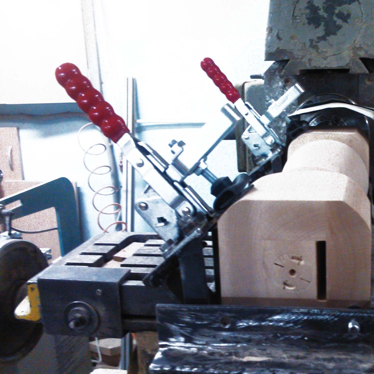
A toggle clamp’s rated holding capacity does not tell you, by itself, how much force reaches the workpiece. That distinction matters in a production fixture: toggle clamp clamping force depends on the linkage and setup, so a high capacity rating alone can’t confirm that a part will stay put or avoid distortion.
To assess the setup, check the clamp’s position, where its spindle contacts the part, and whether the linkage reaches its intended locked position. These details affect the force applied at the workpiece, even when the clamp is operating as intended.
This article explains the difference between holding capacity and clamping force, highlights setup factors to check before a run, and compares vertical and horizontal hold-down, latch, and push-pull straight-line clamps. It also explains how to verify the specifications for the exact model instead of treating a capacity rating as a measurement of workpiece force.
Key Takeaways
- Separate a clamp’s published holding capacity from the force it applies to the workpiece. They describe different things.
- Assess toggle clamp clamping force in context: linkage geometry, handle input, spindle position, and contact point all affect the setup.
- Match the clamp type to the direction of movement and workholding task, then compare specifications for the exact model.
- Before production starts, confirm secure mounting, full engagement, stable contact, adequate workpiece support, and clearance.
Toggle clamp clamping force: what the term means at the workpiece
Toggle clamp clamping force is the force the clamp applies to the workpiece when engaged. It describes the load at the contact point, not simply the number shown as the clamp’s holding capacity.
Clamping force versus holding capacity
Holding capacity is the manufacturer’s specified maximum holding force or capacity for a particular clamp model. Clamping force describes what the workpiece experiences in a given setup. The terms aren’t interchangeable unless the manufacturer’s specifications explicitly say they are.
A published capacity doesn’t tell you the actual force at every contact point. The result depends on the clamp model and how it is installed and adjusted. Treat the capacity as a model-specific rating, not a universal value for every toggle clamp or a direct measurement of workpiece force. Check the manufacturer’s documentation for the rating and any stated test or use conditions.
Why force matters in workholding
Clamping force helps keep a part located against its fixture during machining, fabrication, or assembly. Too little force, or force applied in the wrong direction, can let the part shift. Excessive or poorly directed force can distort a workpiece or load the fixture in an unintended way, particularly when the part has limited support.
For example, a hold-down clamp pressing on a thin plate should work with fixture support beneath the contact area. Without that support, tightening the clamp may deflect the plate instead of holding it flat. Check where the force enters the part and where the fixture reacts to it. That check is more useful than assuming a capacity rating equals the force delivered at the workpiece.
Toggle clamps are one of several clamping tools; their mechanism and application determine how they hold. The next step is understanding how linkage geometry, handle input, and setup affect force at the contact point.
How toggle linkage, handle input, and setup affect clamping force
Setup changes the force at the workpiece by changing how the clamp’s linkage and contact point transfer handle input. The same clamp can behave differently if its spindle position, workpiece location, or alignment changes.
Linkage geometry and mechanical advantage
A toggle clamp’s linkage converts movement and force at the handle into force at the clamping arm or plunger. Mechanical advantage describes how the mechanism multiplies the operator’s input, but it isn’t one fixed value for every clamp. Link lengths, pivot locations, and linkage positions vary by model, so a force estimate needs model-specific geometry and conditions. Don’t infer output force from the clamp type or handle length alone.
As the linkage moves toward its locked position, its geometry affects how force is transmitted. The over-center position helps resist unintended release when the clamp is properly engaged. It doesn’t confirm the force applied to the part or replace checking the model’s rated capacity.
Contact point, spindle, and workpiece position
On a hold-down clamp, changing the adjustable spindle’s height or contact location changes the load path through the arm, workpiece, and fixture. A contact point near the end of an arm can behave differently from one closer to its pivot. The workpiece also needs stable support beneath or opposite the applied force. Without it, the part may move or deflect instead of seating securely.
Align the clamp so its force acts in the intended direction and its contact face sits steadily on the workpiece. Follow the specific model’s instructions for spindle adjustment and engagement. To compare vertical and horizontal hold-down, latch, and push-pull designs, review RMT manual toggle clamp options and check each model’s published details rather than assuming similar linkages deliver the same force.
How to interpret toggle clamp force ratings and choose a suitable type
Choose a clamp based on the required direction of restraint, available fixture space, and the exact model’s published specifications. Category names describe mechanism and arrangement, not a shared force rating. Compare each model’s holding capacity and configuration, and don’t treat the rating as a measurement of force at the workpiece.
Motion and role: The handle is generally vertical when locked; the arm presses downward to secure a part against a fixture.
Verify: Model-specific holding capacity, spindle, base style, mounting details, and clearance.
Motion and role: The handle remains generally horizontal or low-profile when locked; the arm applies downward force.
Verify: Holding capacity, spindle position, mounting orientation, and handle clearance.
Motion and role: A hook or similar component pulls two parts together to secure a closure or joint.
Verify: Holding capacity, compatible latching components, and mounting requirements.
Motion and role: A plunger moves linearly to push or pull a workpiece or fixture component.
Verify: Holding capacity, direction of travel, mounting details, and any compatible accessories.
Match the clamp arrangement to the fixture
Vertical and horizontal hold-down designs differ in handle position and clearance needs, not in a guaranteed amount of force. Select based on fixture layout and operator access. For more on low-profile configurations, see the related guide, Horizontal Toggle Clamps.
Latch and push-pull designs suit different load paths: a latch draws components together, while a push-pull clamp applies force along a plunger’s travel. Confirm alignment, accessory compatibility, mounting requirements, and the exact model’s capacity before selection. Toggle clamp clamping force depends on the complete setup, not the category label alone.
How to check toggle clamp force and setup before using a fixture
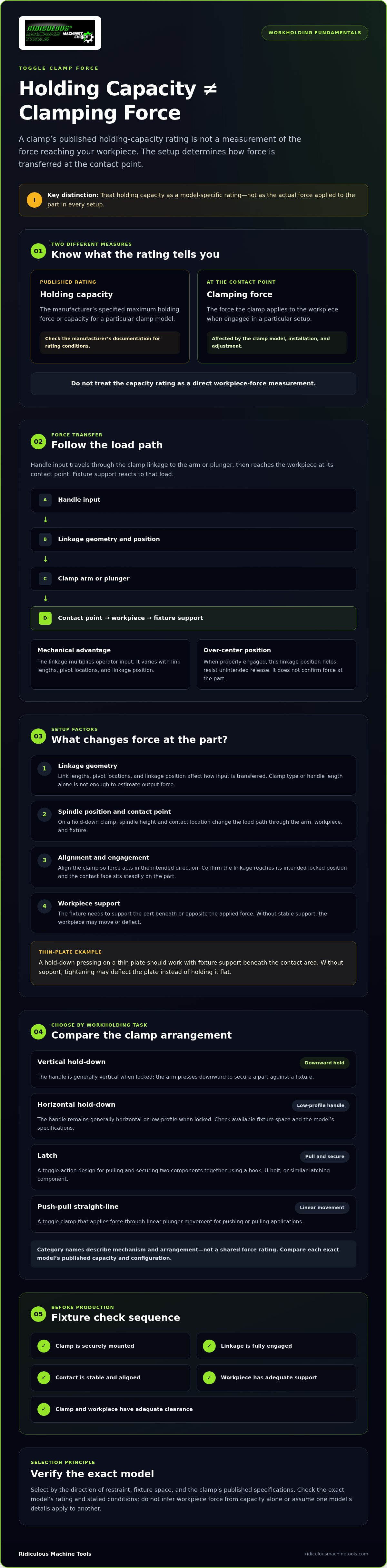
A sound setup check starts with the operation, not a force guess. Machining loads, workpiece stiffness, fixture support, and the direction of applied force all affect whether a clamp suits the job. There’s no universal force target that applies to every fixture.
A practical pre-use setup sequence
- Identify the operation. Determine the direction of the expected load and how the workpiece should locate against the fixture.
- Confirm the clamp model. Check its intended action and published capacity in the manufacturer’s documentation. Confirm that its configuration suits the application.
- Inspect the mounting. Check that the clamp is securely fastened and positioned for the required handle travel. Verify that the spindle contacts the workpiece steadily and at the intended location.
- Check engagement. Move the handle through its full path. Confirm unobstructed operation and the intended locked position, following the manufacturer’s instructions.
Also check that the workpiece is supported against the applied load and that the clamp, handle, and workpiece clear nearby fixture components throughout operation. These checks help determine whether the setup maintains the intended contact without relying on a capacity number as a direct measure of toggle clamp clamping force.
Signs the clamp or setup needs reassessment
Stop and review the setup if the workpiece moves, spindle contact is unstable, the handle or clamp interferes with other components, or the fixture shows visible deflection. Don’t respond by simply increasing force. Recheck the clamp model, load direction, contact location, support, and mounting. If capacity, process suitability, or safe operation is uncertain, consult the clamp manufacturer or qualified technical guidance.
To compare configurations against your fixture requirements, review manual toggle clamp options and verify the specifications for each model.
Selecting an RMT toggle clamp using verified model specifications
Once the fixture layout and clamping direction are clear, compare clamp models by their documented specifications. Ridiculous Machine Tools offers manual toggle clamps in vertical and horizontal hold-down, latch, and push-pull straight-line configurations. These mechanisms suit different workholding arrangements; their category names don’t establish equal capacity or predict the toggle clamp clamping force at a particular workpiece.
Match the clamp mechanism to the workholding task
Start with the movement the fixture needs. A hold-down clamp presses a workpiece toward its support. A latch toggle clamp pulls components together with a hook or similar latching component. A push-pull straight-line toggle clamp applies force through linear plunger movement. Check mounting space, handle or plunger approach, clearance through the operating path, and the location and stability of workpiece contact. These factors help narrow the mechanism, but suitability still depends on the specific model and operating conditions.
Review model specifications before purchase
RMT specifications vary by model and configuration. On the product page for the exact clamp, verify:
- Published holding capacity, without treating it as the force applied at the workpiece
- Material and spindle details
- Base style and mounting requirements
- Compatibility of any hook, spindle, or replacement accessory with the clamp model
Check the mounting interface and accessory fit before ordering replacement components. If the published information doesn’t resolve a capacity or compatibility question, confirm it with the manufacturer rather than inferring an answer from a similar clamp.
Browse Ridiculous Machine Tools’ manual toggle clamp category to compare available mechanisms, then review the specifications for the exact model before selecting it for a fixture.
Set Up for Consistent Clamping
For a dependable production setup, evaluate the force at the workpiece rather than relying on a holding-capacity rating alone. Linkage geometry, contact position, mounting, and workpiece support all affect how a toggle clamp performs. Before the run, confirm the exact model, check its published specifications, and verify that the clamp engages and clears the fixture as intended.
Ridiculous Machine Tools offers horizontal and vertical hold-down, latch, and push-pull straight-line manual toggle clamps. Product specifications vary by model, so check the applicable product page for holding capacity, material, spindle, base style, and mounting requirements.
Use these checks to make an informed decision about toggle clamp clamping force and the workholding arrangement. Browse Ridiculous Machine Tools manual toggle clamps and compare model details against your fixture requirements.
Frequently Asked Questions
Is toggle clamp holding capacity the same as clamping force?
Not automatically. Holding capacity is the manufacturer’s specified maximum holding force or capacity for a particular clamp. Clamping force is the force applied to the workpiece during clamping. The terms may be related, but don’t treat them as interchangeable unless the product documentation supports that interpretation. Check how the manufacturer defines the rating for the exact clamp model before applying it to a fixture.
How do you increase a toggle clamp’s clamping force?
First confirm the clamp is suitable for the application and mounted correctly. Handle input, linkage geometry, spindle adjustment, and contact position affect force at the workpiece, but setup changes don’t raise the clamp’s verified rating. Don’t force the handle or modify the mechanism to pursue more force. Follow the manufacturer’s instructions and reassess the clamp and fixture if the workpiece doesn’t stay secure.
Can a toggle clamp’s rated capacity predict its force on a workpiece?
A capacity rating describes a specified capability of a particular model, but it doesn’t establish the force delivered to every workpiece. Linkage geometry, adjustment, contact location, and fixture arrangement affect force at the contact point. Read the rating within the conditions stated by the manufacturer. Don’t use it as a substitute for application-specific engineering or testing when the process requires that assessment.
What affects toggle clamp clamping force?
Toggle clamp clamping force depends on the mechanism and linkage geometry, the input applied at the handle, spindle or contact adjustment, and the point where the clamp meets the workpiece. Fixture support and workpiece position also affect how the load is carried. These variables differ by model and setup, so generic estimates can’t replace verified product information or an application-specific review.
Are horizontal and vertical hold-down toggle clamps rated for the same force?
Don’t assume they are. Horizontal and vertical hold-down clamps differ in handle position, and individual models may also differ in capacity, base, and spindle configuration. Compare the manufacturer’s specifications for the exact models under consideration. Select based on clamping direction, fixture mounting, available clearance, and verified capacity, not orientation alone.
How can I tell if a toggle clamp is holding a workpiece securely?
Check that the clamp is securely mounted, makes stable contact, and reaches its intended locked position without interference. During the intended operation, watch for workpiece movement or visible fixture deflection, and reassess the setup if either occurs. A visual check alone doesn’t establish a safe force value. Use the model documentation and qualified process guidance to assess suitability for the application.
Article by
Ridiculous Machine Tools Technical Team
The Ridiculous Machine Tools Technical Team provides practical information about precision machine tooling, CNC tooling, workholding, and related manufacturing applications. RMT focuses on helping machinists, manufacturers, fabricators, and other customers understand tooling specifications, compatibility, selection, and proper application. Our technical content draws on product specifications, industry knowledge, and RMT's quality-control experience to provide clear, useful information for selecting and using machine tooling and workholding products.
Ridiculous Machine Tools — Machinist's Choice™