

Dynamic Balancing CAT40 Toolholders Above 12,000 RPM
Posted by RMT on Nov 5th 2026
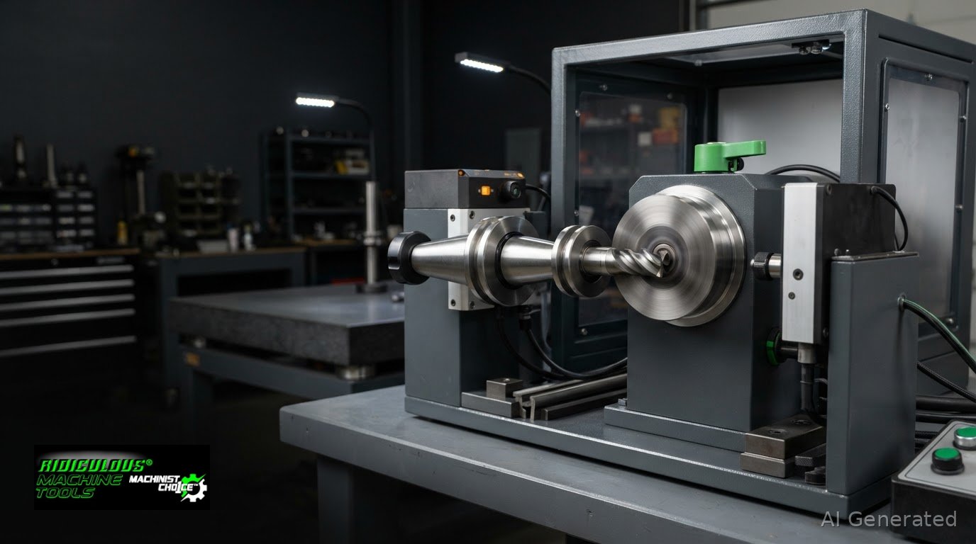
A CAT40 holder’s RPM rating alone doesn’t determine whether dynamic balancing of CAT40 toolholders above 12,000 RPM is appropriate; the complete assembly and machining demands matter. This article explains how ISO balance grades relate to residual unbalance and what to consider when selecting a high-speed setup.
Key Takeaways
- Judge balancing needs by the complete rotating assembly, spindle speed, and machining demands, not the CAT40 holder’s RPM rating alone.
- Learn how imbalance can affect vibration, surface finish, and cutting-edge wear, especially as spindle speed rises.
- Understand what an ISO balance grade tells you about residual unbalance, and why the grade must be considered alongside operating speed.
- Compare the roles of ISO 21940 and ISO 16084 to make a more informed decision about balancing toolholder assemblies for your application.
What Are Some Common Tool Balancing Standards?
ISO 16084 addresses rotating tools and tool systems, including permissible unbalance and static or dynamic balancing. ISO 21940 covers balance quality grades for rotating machinery. These standards describe balance criteria, not one universal CAT40 speed limit. Some industry guidance suggests balancing toolholders at 8,000 RPM to support tool life and finish. The right criterion depends on the complete setup and machining demands.
Imbalance can produce vibration during rotation. At 18,000 RPM, spindle bearings experience cyclic loading 300 times per second. Vibration can affect surface finish and contribute to uneven cutting loads. Increased runout can distribute chip load unevenly, accelerate edge chipping, and concentrate thermal stress on one cutting edge. Measure runout and assess balance separately; one measurement does not establish the other.
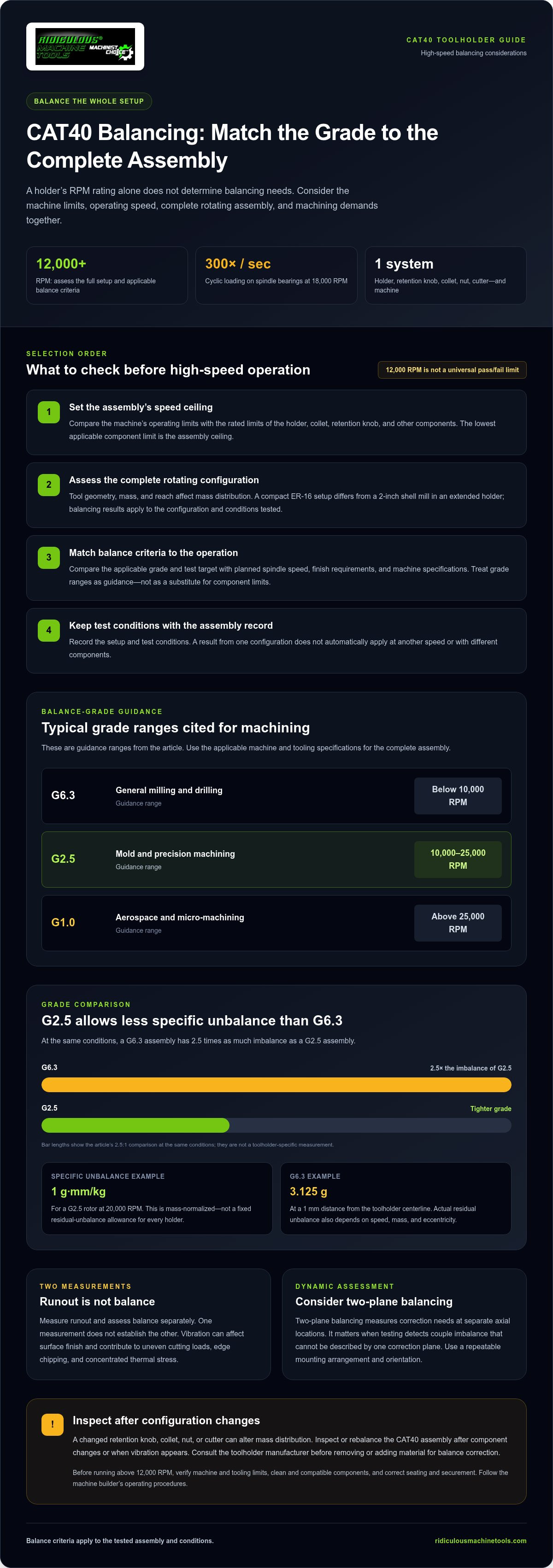
Select a holder by its specified speed and balance criteria, tool geometry, and machining task. A short, compact ER-16 setup differs from a 2-inch shell mill in an extended holder because their mass distributions differ. Guidance lists G6.3 for general milling and drilling below 10,000 RPM, and G2.5 for mold and precision machining at 10,000-25,000 RPM. These ranges are guidance, not a substitute for applicable machine and tooling specifications.
Rebalance or inspect a CAT40 assembly after changing components, such as the retention knob, collet, nut, or cutter, or when vibration appears. The changed configuration can alter mass distribution. Consult the toolholder manufacturer before removing or adding material for balance correction.
Before running above 12,000 RPM, compare the machine tool’s operating limits with the specifications for the complete tooling setup. Check that the taper and components are clean, compatible, and correctly seated and secured. Follow the machine builder’s operating procedures. These checks confirm setup conditions; balancing evaluates mass distribution.
Balancing toolholder assemblies at high spindle speeds
Dynamic balancing evaluates rotating behavior, not just a holder’s static condition. For dynamic balancing of CAT40 toolholders above 12,000 RPM, the test setup should reflect the assembly and operating conditions being assessed.
In the United States, balancing cost depends on the service scope, the assembly tested, and the required test conditions. A holder-only assessment differs from testing a configured tool system.
Dynamic Balance and High-Speed Vibration
Dynamic balancing measures how mass is distributed in a rotating assembly. A balancing machine can identify vibration associated with that distribution, but surface finish alone cannot reveal its cause. Compare the machine’s readings with the applicable balance criteria before deciding whether correction is needed.
Spindle Speed and Balancing Needs
Balancing results apply to the configuration and conditions used for the measurement. Compare the test target with the intended spindle speed and the machine’s operating limits. A result from one setup does not automatically apply at another speed or in another configuration, so record the test conditions with the assembly identification.
Two-Plane Balancing at Operating Speed
Two-plane balancing measures correction needs at separate axial locations. This is relevant when testing detects couple imbalance that cannot be described by a single correction plane. The balancing machine’s mounting arrangement and the assembly’s orientation affect how readings are interpreted, so use a repeatable setup to support useful production decisions.
Balancing Thresholds for High-Speed Spindles
Recommendations use different speed thresholds, so treat them as screening guidance rather than a universal pass-or-fail rule. For dynamic balancing of CAT40 toolholders above 12,000 RPM, compare the machine’s specified limits, the tool system’s balance criteria, and the operation’s finish requirements. Document the selected criteria so later setups follow the same basis.
For milling setups using CAT40 tooling, compare compatible CAT40 end mill holders against the application’s requirements.
ISO 1940-1 balance grades and residual unbalance
ISO 21940, formerly ISO 1940-1, describes balance quality grades for rotating machinery. A grade helps relate rotor mass, operating speed, and permissible residual unbalance, but it does not set one universal CAT40 RPM limit.
The maximum RPM for a CAT40 toolholder assembly depends on the machine and the rated limits of its holder, collet, retention knob, and other components. Use the lowest applicable component limit as the assembly ceiling.
Balancing Tolerances and Quality Grades
A balance grade expresses allowable specific unbalance for a rotor at its operating speed. Under ISO 1940-1, a G2.5 rotor at 20,000 RPM may have specific unbalance of 1 g mm/kg. That value is mass-normalized, not a fixed residual-unbalance allowance for every toolholder.
Residual unbalance is the mass eccentricity remaining after balancing. In manufacturing and grinding, a tighter balance grade may be relevant as speed and finish demands rise, but the permissible amount also depends on the tooling’s mass and geometry.
RPM Ranges for Balance Grades
Balance-grade selection links rotor quality to intended speed and operation. Guidance lists G6.3 for general milling and drilling below 10,000 RPM, G2.5 for mold and precision machining at 10,000-25,000 RPM, and G1.0 for aerospace and micro-machining above 25,000 RPM.
Use these ranges as a guide, not as a substitute for the toolholder’s specification or the machine’s limits. Match the grade to the complete assembly and planned operation, including the cutting tool’s mass and reach.
Comparing G2.5 and G6.3
G2.5 permits less specific unbalance than G6.3 at the same conditions. A G6.3 assembly has two and a half times as much imbalance as a G2.5 assembly, making G2.5 the tighter grade for higher-speed precision work.
For example, at a 1 mm distance from the toolholder centerline, G6.3 allows 3.125 grams of imbalance. That figure illustrates why grade alone cannot define an assembly’s residual unbalance: speed, mass, and eccentricity all matter in actual machining.
ISO balancing standards for toolholders
ISO standards distinguish general rotor balance from requirements for cutting tools and tool systems. For a CAT40 setup, the key is applying the right standard to the complete assembly, not treating a holder’s balance grade as the entire answer.
ISO 16084:2017 addresses balancing rotating tools and tool systems, including permissible unbalance and static and dynamic balancing. That tool-system focus matters because a milling assembly can include the holder, collet, nut, retention knob, and cutting tool. Each component contributes mass and can change the assembly’s balance state.
ISO 21940-11 specifies balance quality requirements for rigid rotating machinery, including permissible residual unbalance relative to maximum operational speed. It offers a framework for interpreting rotor balance, but toolholder selection also needs the tool-system context covered by ISO 16084. Don’t treat a grade as a stand-alone RPM approval for every CAT40 configuration.
ISO 16084 illustrates how application criteria affect allowable balance. In an HSK-A63 example, the balancing-machine tolerance, Ubm,tol, is 0.75 g.mm. The example uses a balancing factor, fbal, of 0.8 for standard machining and 0.2 for fine machining. Those figures belong to that example, not a CAT40 specification. The lower fine-machining factor reflects a tighter balance criterion for that stated application.
ISO 14694 addresses flexible rotors with a maximum speed of 15,000 RPM. Its scope differs from tool-system balancing, so it should not be substituted automatically for ISO 16084 when assessing cutting tooling. The practical takeaway: identify whether the specification covers a rotor or the assembled tool system, then match its balance criteria to speed and machining purpose. A balancing machine result is useful only when its test configuration and criteria correspond to the assembly being evaluated.
Compare ER collet chuck configurations
Ridiculous Machine Tools: Horizontal Toggle Clamps
Ridiculous Machine Tools supplies manual toggle clamps for fixture and workholding tasks, a separate shop need from balancing a CAT40 toolholder assembly. Horizontal Toggle Clamps suit setups where a low-profile handle position is useful; Latch Toggle Clamps, Vertical Toggle Clamps, and Push-Pull Straight Line Toggle Clamps provide different clamping actions and configurations.
Choose a clamp based on how the workpiece needs to be held and how the fixture is arranged. A hold-down application requires a different configuration from a latch or straight-line push-pull task. Match the clamp style to the fixture’s movement and mounting requirements; toggle clamps are not a tool-balancing method.
For CAT40 balancing, use the assembly’s balance specification and machining requirements to guide the tooling decision. For fixture workholding, visit ridiculousmachinetools.com to explore Ridiculous Machine Tools’ manual toggle clamp options.
Make the next setup decision repeatable
Make balancing decisions part of a repeatable shop process. For each high-speed setup, keep a controlled configuration record identifying the holder and installed components, as well as the job or operation. If the setup changes, flag it for review rather than assuming the earlier assessment still applies.
Assessing dynamic balancing of CAT40 toolholders above 12,000 RPM is most useful when the recorded setup matches the assembly that will actually run. That discipline helps machinists compare repeat jobs and investigate vibration changes across shifts. A shared record also gives programming, setup, and purchasing teams a common reference when tooling changes or production requirements shift.
Apply the same clear decision-making to other tooling and workholding needs. Keep setup records practical, readable, and aligned with established shop procedures. A consistent process makes future tooling decisions easier to communicate and act on.
Build a clear process, then put it to work with confidence.
Frequently Asked Questions
Toolholder Balancing: What RPM, Which Tools, Why Bother?
Balance deserves attention as spindle speed, tool reach, and assembly asymmetry increase. Some industry guidance suggests balancing toolholders at 8,000 RPM, while the machine builder’s limits and the assembly’s specified balance grade remain important. A long cutter or offset feature can change mass distribution. In practice, prioritize high-speed finishing setups and notably asymmetrical tooling, then assess the complete configuration.
What Does Angular Momentum Have to Do With Tool Balancing?
Angular momentum describes the motion of a rotating body and equals its moment of inertia multiplied by angular velocity. It helps explain why mass distribution matters: an asymmetrical assembly rotating faster produces greater dynamic effects. For example, an extended tool and a compact tool can behave differently even in CAT40 holders. Angular momentum is not a balance grade or a direct measure of runout.
What Considerations Should Be Taken When Tool Balancing?
Assess the full setup, including the holder, retention knob, collet, nut, and cutting tool. Record tool length, mass distribution, intended spindle speed, and whether the machining task emphasizes roughing or fine finishing. Treat runout and balance as separate checks because they describe different conditions. Before removing or adding holder material to correct balance, consult the toolholder manufacturer.
What Balance Grade Is Recommended for CAT40 Toolholders Operating Above 12,000 RPM?
G2.5 is listed as suitable for mold and precision machining from 10,000 to 25,000 RPM, making it a useful reference for some CAT40 high-speed applications. It is not a universal prescription: the complete assembly, machine limits, and operation determine the appropriate specification. Confirm that the stated grade applies to the holder or assembled tool system you plan to run.
How Do You Dynamically Balance a CAT40 Toolholder and Cutting-Tool Assembly?
Balance the configuration that will actually rotate: assemble the compatible holder, retention knob, collet, nut, and cutter, then have the assembly evaluated on a suitable balancing machine against its intended operating conditions and target grade. Reconfigure and reassess if any component changes. Do not drill or grind the holder as a correction method without guidance from the toolholder manufacturer.
What Is the Difference Between G2.5 and G6.3 Balance Grades for High-Speed Milling?
G2.5 is the tighter balance grade; under the same conditions, a G6.3 assembly has two and a half times as much imbalance. Guidance associates G6.3 with general milling and drilling below 10,000 RPM, and G2.5 with mold and precision machining at 10,000-25,000 RPM. Treat these ranges as selection guidance, not a substitute for the assembly specification.

Article by
Ridiculous Machine Tools Technical Team
The Ridiculous Machine Tools Technical Team provides practical information about precision machine tooling, CNC tooling, workholding, and related manufacturing applications. RMT focuses on helping machinists, manufacturers, fabricators, and other customers understand tooling specifications, compatibility, selection, and proper application. Our technical content draws on product specifications, industry knowledge, and RMT's quality-control experience to provide clear, useful information for selecting and using machine tooling and workholding products.
Ridiculous Machine Tools — Machinist's Choice™