Clamps horizontales Best Practices and Expert Advice
Posted by RMT on Nov 3rd 2026
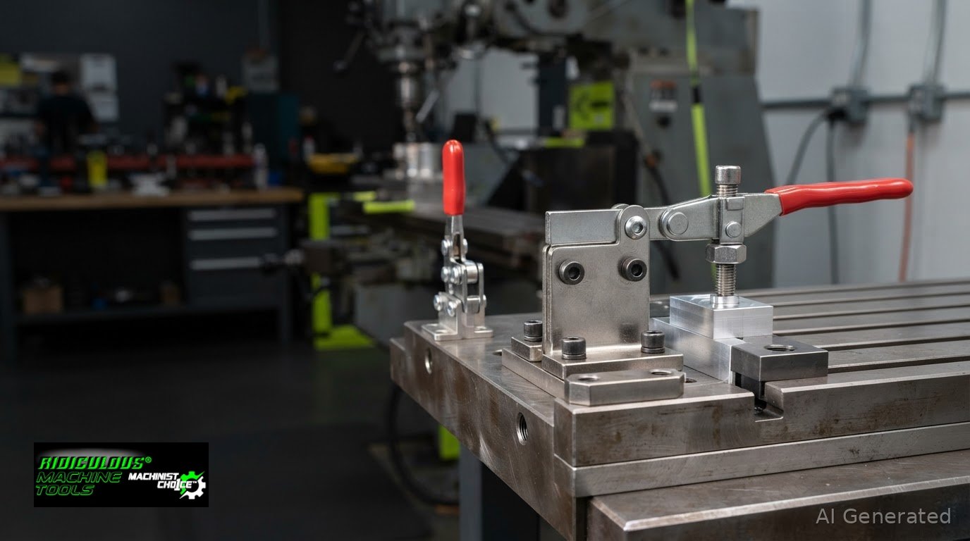
The main difference is handle position: a horizontal hold-down clamp locks with its handle roughly parallel to the base, while a vertical model locks with an upright handle. The low profile can suit fixtures with limited overhead clearance, but it does not automatically make this style the right choice. Select based on clearance, mounting space, operator access, and the forces the fixture must resist.
Both styles apply downward pressure through a toggle linkage, but rated holding capacity and clamping force are not the same. Each clamp needs a stable mounting surface and a clear operating path. Compare how handle layout affects access, how to assess force requirements, and how the base configuration shapes installation. Use these criteria to match a clamp to your fixture rather than choosing by profile alone.
Key Takeaways
- Rate a clamp for the forces the operation creates, not just the workpiece’s weight; holding capacity and applied clamping force are different measures.
- Compare handle travel and over-center linkage position to judge clearance, access, and how the clamp stays engaged.
- Choose a mounting base that fits the fixture’s available width and mounting face before finalizing clamp placement.
- Match clamp style to the direction of force: hold-down, latching, and straight-line applications call for different configurations.
Holding and clamping force definitions
Holding capacity and clamping force describe different aspects of toggle-clamp workholding. Size the clamp for process forces, then consider how its linkage transfers operator input to the workpiece.
Holding Capacity Versus Clamping Force
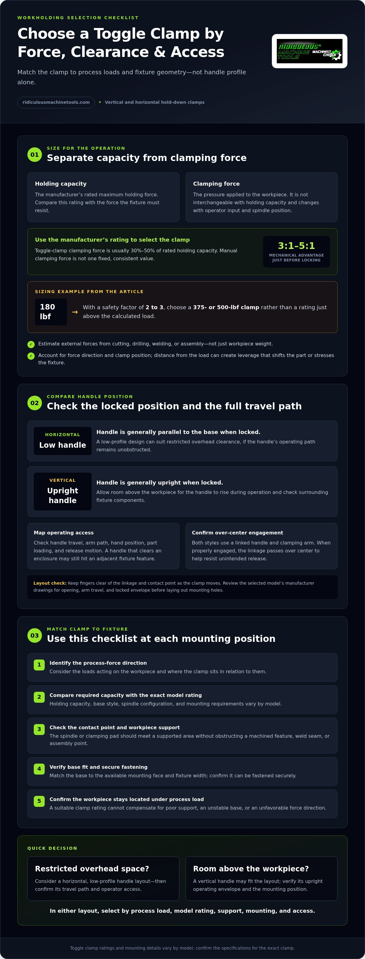
Holding capacity is the manufacturer’s rated maximum holding force; clamping force is the pressure applied to the workpiece. They are related, but not interchangeable. Toggle-clamp clamping force is usually 30% to 50% of rated holding capacity, depending on operator input and spindle position. Compare the rated capacity with the load the fixture must resist, rather than treating that rating as the pressure at the contact point.
Process Forces and Clamping Force
Process forces include loads created by cutting, drilling, welding, or assembly. Base clamp capacity on those forces and their direction, not solely on workpiece weight. The clamp’s position relative to the load affects how well the setup resists movement. A horizontal hold-down clamp positioned far from the cutting-force path may create leverage that shifts the part or stresses the fixture.
For a practical sizing sequence, estimate the external forces acting on the workpiece, then multiply them by a safety factor of 2 to 3 to calculate required holding capacity. The margin accounts for variation in loads and fixture conditions. For example, a 180 lbf requirement calls for a 375- or 500-lbf clamp, rather than choosing a rating just above the calculated load.
Do not assume a manual clamp applies a fixed clamping force. Operator input and spindle position change the force, so manual clamping force cannot be correctly measured as a single consistent value. Toggle linkages can provide mechanical advantage of 3:1 to 5:1 just before locking. Use the manufacturer’s holding-capacity rating to select the clamp, and consider contact position and workpiece support when arranging the fixture.
Once mounted, confirm that the clamp seats securely and the workpiece stays located under the operation’s process load. A suitable rating cannot compensate for poor fixture support, an unstable base, or an unfavorable force direction.
Vertical vs Horizontal Toggle Clamps: What’s the Difference?
Handle position distinguishes horizontal from vertical toggle clamps. Compare each clamp’s locked position, handle travel, and clearance with the fixture layout.
Toggle Mechanism and Handle Position
Both designs use a linked handle and clamping arm. Moving the handle pivots the arm toward or away from the workpiece. At the locked position, the linkage passes over center, helping resist unintended release when properly engaged. Check the clamp’s full opening and closing path, not just its final position. That travel determines access for loading parts and operating the handle.
Horizontal and Vertical Handle Orientation
A horizontal hold-down clamp has a low handle position, generally parallel to its base when locked. A vertical hold-down clamp’s handle is generally upright when locked. On a vertical model, the handle typically lies flat and parallel to its clamping arm when disengaged. Lifting it engages the mechanism and applies downward pressure. Compare both positions with surrounding fixture components.
Overhead clearance is a key difference. A vertical handle needs room above the workpiece as it rises during operation. A low-profile horizontal design can suit a fixture beneath a guard, shelf, or machine enclosure, provided the handle’s path remains clear. For example, check whether the handle can reach its locked position without contacting a nearby plate or adjacent clamp.
Also map the clamping arm’s path and the operator’s hand position. Leave room to open the toggle fully, load the workpiece, and release the clamp without reaching across an obstruction. Keep fingers clear of the linkage and contact point as the clamp moves. A handle that clears the enclosure but strikes a neighboring fixture feature still creates an access problem. Review the selected model’s manufacturer drawings before laying out mounting holes, including the clamp’s opening, arm travel, and locked envelope.
Choosing between vertical and horizontal clamps
Choose an orientation that matches the fixture’s clearance and access needs to the workpiece position. For production setups, consider how operators load and release parts at each station.
Comparing Clamp Specifications
Compare each model’s holding capacity, base style, spindle configuration, and mounting requirements. These details vary by model, so review the specifications for the exact clamp you are considering. Then map its mounting position against the direction of process forces. A clamp near the load may resist movement differently from one mounted farther away.
Check the workpiece contact surface. The spindle or clamping pad should meet a supported area without obstructing a machined feature, weld seam, or assembly point. For production workholding, compare the required holding capacity with the model’s published rating. Confirm that the base can be fastened securely to the fixture plate.
Choosing a Hold-Down Clamp Orientation
A low-profile hold-down model keeps its handle near the fixture surface when locked, which can suit restricted overhead clearance. A vertical model places its handle upright when engaged, so its operating envelope needs room above the part. Select based on the actual mounting position, nearby tooling, and operator loading path.
For manual workholding, include the operator’s approach and release motion in the layout. A low-profile design may fit beneath an enclosure, while an upright handle may work on an open bench. Check the specific model’s handle travel and mounting face before drilling the fixture plate. Low-profile toggle clamp options can help compare configurations for restricted-clearance layouts.
Use this selection sequence at each fixture position:
- Identify the process-force direction and supported contact surface.
- Compare required capacity with the specific model’s published rating.
- Check mounting geometry, handle travel, and operator access.
A mixed fixture can use low-profile clamps at restricted stations and vertical models where clearance allows. Match each position to its local access and mounting conditions, then assess the complete production cycle.
Mounting base and clamping variations
Choose a base that fits the fixture face and leaves room for the arm, handle, and workpiece. Match the mounting style to the available surface before laying out holes.
Mounting Styles and Fixture Geometry
Flat-base models suit general mounting on a fixture’s top plate. Narrow-base designs fit fixtures with restricted mounting width, while side-mount versions fasten to a vertical face. Select the base to match the fixture geometry, then check that the arm reaches the part without contacting machine components.
For a fixture holding several workpieces, map each clamp position before drilling. Keep the contact point over a supported area and confirm the base sits fully against its mounting face. A clamp placed too close to a neighboring station can obstruct loading or interfere with adjacent handle travel.
Clamp Types, Installation, and Adjustment
Available configurations include flat-base, narrow-base, and side-mount toggle clamps. Choose according to fixture geometry and the direction of operator access to the workpiece.
To install a clamp, align its base holes with the fixture pattern and fasten it using hardware suited to the clamp and fixture. Adjust the spindle or clamping pad to contact the workpiece when the toggle is locked. Move the handle through its full opening and closing path, confirming free movement and stable part location.
Before production, inspect the mounting interface with the workpiece in place. Confirm that the base remains stable and the contact pad lands on a supported surface, not a thin edge or unsupported overhang. On a machine fixture, check clearance in both open and locked positions. Hole spacing, fastener requirements, and dimensions depend on the specific model, so use its product details to prepare the fixture pattern.
After adjustment, check contact across the intended workpieces. Reassess the setup if the part geometry or fixture layout changes.
Compare horizontal toggle clamp configurations
Ridiculous Machine Tools: Horizontal Toggle Clamps
Ridiculous Machine Tools supplies horizontal toggle clamps for fixtures where a low handle position suits the available clearance. Compare the specific model’s holding capacity, base style, and mounting requirements with your fixture and process loads before selecting. These details vary by model, so match the published specifications to the intended workholding setup.
For other force directions or fastening arrangements, Ridiculous Machine Tools also offers vertical toggle clamps, latch toggle clamps, and push-pull straight-line toggle clamps. These configurations suit different fixture layouts and motions, including hold-down, joining components, or applying linear push-pull force. Choose the clamp style that matches the required motion and mounting geometry.
Visit Ridiculous Machine Tools to browse horizontal toggle clamps.
Put Your Clamp Selection Into the Fixture Plan
Make the selection useful beyond the initial setup by recording the chosen clamp model, mounting location, and workpiece contact point in the fixture documentation. This gives machinists and operators a consistent reference when a job returns to production or a fixture needs maintenance. If the part geometry or process changes, reassess whether the original horizontal clamps still suit the updated setup.
Ridiculous Machine Tools offers Horizontal Toggle Clamps, Vertical Toggle Clamps, and Latch Toggle Clamps for different workholding layouts. Use the product details to compare configurations with your fixture requirements, then choose the category that matches the required motion and mounting arrangement. A deliberate selection helps keep procurement aligned with the fixture design.
Contact Ridiculous Machine Tools
With the fixture plan documented, your team has a clear starting point for repeatable workholding decisions.
Frequently Asked Questions
What are horizontal clamps and what are they used for?
Horizontal clamps are manually operated hold-down devices with a handle that stays low when locked. They secure parts on fixtures, jigs, and work surfaces during tasks such as machining, welding, assembly, and woodworking. For example, a fixture beneath a machine enclosure may benefit from a clamp whose handle does not need to rise vertically during operation.
How do horizontal toggle clamps work?
A horizontal toggle clamp transfers handle movement through linked pivots to move its clamping arm against a workpiece. As the linkage passes over center, it resists unintended opening when properly engaged. During setup, position the contact pad against a supported area of the part. Then move the handle through its range and confirm the part remains seated.
How do I choose the right horizontal clamp for my application?
Start with the operation and fixture layout, then compare the clamp’s rated holding capacity, base style, spindle arrangement, and required mounting surface. For a fixture with a narrow rail, a narrow-base model may fit better than a flat-base model. Also consider the workpiece contact point, operator access, and handle clearance throughout loading and release.
What are the load capacities and clamping forces of horizontal clamps?
Holding capacity and applied clamping force are different ratings. Toggle-clamp clamping force is usually 30% to 50% of rated holding capacity, depending on operator input and spindle position. The correct capacity depends on the process load and clamp placement. Use the manufacturer’s rating for the specific model, and account for the direction of machining, welding, or assembly forces.
What materials and sizes do horizontal clamps come in?
Horizontal toggle clamps come in different model dimensions, base configurations, and materials. Ridiculous Machine Tools offers carbon-steel and 304 stainless-steel toggle clamp models where identified for the specific product. Compare the model’s published construction, mounting dimensions, spindle configuration, and capacity with the fixture design. Material choice should reflect the operating environment, including exposure to moisture or coolant.
How much do horizontal clamps cost in the United States?
The clamp model and its configuration, including base style, material, and rated holding capacity, determine its price. Ridiculous Machine Tools lists current prices with individual product listings, so buyers can compare the specific models they are considering. Check the listing for the selected clamp rather than relying on an average, since different configurations suit different fixture requirements.
Article by
Ridiculous Machine Tools Technical Team
The Ridiculous Machine Tools Technical Team provides practical information about precision machine tooling, CNC tooling, workholding, and related manufacturing applications. RMT focuses on helping machinists, manufacturers, fabricators, and other customers understand tooling specifications, compatibility, selection, and proper application. Our technical content draws on product specifications, industry knowledge, and RMT's quality-control experience to provide clear, useful information for selecting and using machine tooling and workholding products.
Ridiculous Machine Tools — Machinist's Choice™