

CAT40 Pull Stud Torque Specs & Inspection Guide
Posted by RMT on Oct 30th 2026
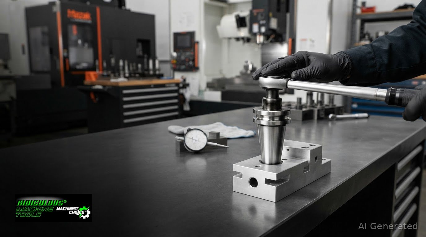
Torque recommendations can vary by machine and retention knob, so use the specification applicable to the installed setup. The right approach to CAT40 pull stud torque specifications and inspection frequency starts with the installed spindle and compatible retention knob, then follows machine-specific maintenance guidance instead of copying a general value across machines. This guide compares traditional torque figures by taper, explains why CAT40 and BT40 retention hardware should not be assumed interchangeable, and covers the effects of excessive tightening. It also outlines inspection criteria, service-life considerations, and how to keep maintenance records useful across shifts. The aim is a practical reference for consistent torque decisions, with reported shop practices kept distinct from the setting that applies to your machine.
Key Takeaways
- Set retention-knob torque from the machine manufacturer’s specification; published CAT40 values vary, so a generic setting can be misleading.
- Compare torque by taper size and interface. CAT40 and BT40 specifications aren’t automatically interchangeable.
- Build pull-stud checks into scheduled maintenance, and replace studs showing wear or damage.
- Avoid excessive tightening: it can distort spindle geometry, increase runout, or damage a retention knob.
What torque do you recommend tightening the retention knobs?
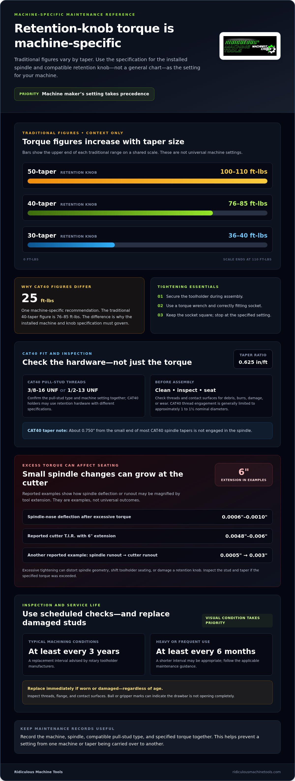
For a CAT40 retention knob, use the torque specified by the machine tool manufacturer for that spindle and knob. One machine-specific recommendation is 25 ft-lbs, while the traditional figure for a 40-taper retention knob is 76-85 ft/lbs. Those values differ substantially, so neither is universal. The machine’s own setting takes priority over a general shop rule.
Use a torque wrench with a suitable range and a socket that fits the pull stud. This provides a repeatable torque value, unlike tightening by feel. Keep the socket square to the retention knob and stop when the wrench reaches the specified setting. A CNC tightening fixture can support a toolholder during assembly, but it does not replace torque control.
Traditional values vary by taper: 30-taper retention knobs are listed at 36-40 ft/lbs, 40-taper at 76-85 ft/lbs, and 50-taper at 100-110 ft/lbs. These figures describe traditional practice, not the required setting for every machine. Confirm the applicable value for the spindle and knob combination before tightening.
Material and heat treatment affect a retention knob’s strength and wear resistance. Match the knob to the toolholder and spindle requirements; appearance alone does not confirm its material or heat treatment. MegaFORCE is a named retention-knob design, but the name alone does not establish its torque value, material, hardness, or test results. Refer to the applicable manufacturer’s specifications for those details.
Inspect pull studs during scheduled maintenance. Check the threads, flange, and contact surfaces for visible wear or damage. Ball or gripper marks can indicate that the drawbar is not opening completely; replace the stud immediately. Replace any stud with visible wear as well.
For typical machining conditions, rotary toolholder manufacturers advise replacing pull studs at least every three years. Heavy or frequent use may call for replacement at least every six months. These intervals supplement visual inspection. Replace a stud with visible wear or damage regardless of its age.
Pull-stud torque specifications by taper size
Traditional torque figures change with taper size, but they aren’t universal machine settings. The CAT40 pull stud torque specifications and inspection frequency for a particular machine should follow its maintenance guidance and the compatible retention knob.
Torque Values Across Taper Sizes
Traditional figures are 36-40 ft/lbs for 30-taper retention knobs, 76-85 ft/lbs for 40-taper, and 100-110 ft/lbs for 50-taper. The differences reflect taper size; they don’t authorize transferring a value between spindle systems. Apply the value specified for the machine and knob combination. A chart for another taper may provide context, but it cannot set the installed machine’s torque.
CAT40 Threads and Taper Engagement
CAT40 pull studs use either 3/8-16 UNF or 1/2-13 UNF threads, and the taper ratio is 0.625 in/ft. Thread engagement is generally limited to approximately one to one and a half nominal diameters. About 0.750 inches from the small end of most CAT40 spindle tapers isn’t engaged in the spindle. Before assembly, inspect threads and contact surfaces for damage or debris, then clean them so the parts seat properly.
Manufacturer and Machine Variations
Yes. Torque can vary by machine tool and pull-stud manufacturer because retention-knob design and spindle requirements differ. Use the machine maker’s value for the installed spindle and compatible knob, rather than carrying over a setting from another machine. Even holders sharing the CAT40 designation may use retention hardware with different specifications. Keep the pull-stud type and machine setting together in maintenance records.
Torque Units and Tightening Procedure
Use the torque unit specified by the machine maker, commonly ft-lbs, and apply it with a torque wrench. Seat a correctly fitting socket squarely on the knob, and secure the toolholder during tightening. Before inspection, remove loose debris and wipe the threads and contact surfaces clean. Check for damaged threads, burrs, or wear before reinstalling the pull stud.
Risks of excessive tightening
Over-tightening a CAT40 retention knob can distort the spindle taper and shift toolholder seating. One reported case measured spindle-nose deflection of 0.0006"-0.0010" after excessive torque. Even small changes at the spindle can affect cutter position, runout, and machining results. The holder may appear seated while its contact geometry has changed.
Extension magnifies the effect at the cutting edge. A reported example describes 0.0008" of spindle deflection becoming 0.0048"-0.006" TIR at the cutter with a 6-inch extension. Another example shows 0.0005" of spindle runout becoming 0.003" at the cutter over the same extension. Long tool assemblies make taper condition especially consequential.
Excessive tightening can damage the retention knob. Reports describe pull studs cracking below the flange, particularly through-coolant studs, and fretting when a stud sits within the taper contact area. These failures can compromise retention and leave debris or damaged contact surfaces. If tightening exceeded the machine’s specified value, inspect the stud and taper.
Use the machine maker’s torque specification, not a setting copied from another spindle. One shop reported setting its CAT40 torque wrench to 35 ft-lbs, while another account described 45-65 ft-lbs as common over-torquing. Such reports illustrate differing shop practice, not a universal target. A torque wrench helps control the applied load; a hand wrench cannot establish a repeatable value. Stop at the specified setting rather than adding force for extra security. If a knob loosens or shows damage, assess its threads and seating surfaces before returning the holder to service.
A forum participant reported witnessing fretting after overtightening when a pull stud was positioned within the taper contact area. This firsthand account is not a quantified test result: it establishes neither a torque threshold nor that every pull stud will fret. Its relevance is limited to the described condition, where the stud’s position relative to the taper contact area matters. Check any damaged or marked contact region when investigating suspected overtightening, but do not treat this observation as a universal failure rule.
CAT40 and BT40 pull stud torque specifications
CAT40 and BT40 pull studs don’t have one interchangeable torque value. Published CAT40 reports range from 40 ft-lbs in one shop to charts listing no CAT40 value below 85 ft-lbs. Treat these as reported differences, not universal recommendations. For a specific machine, its maintenance documentation provides the applicable torque and inspection guidance.
BT40 and CAT40 holders use different interface conventions, so the label “40 taper” alone doesn’t establish that their pull studs are interchangeable. One reported measurement places an inch CAT taper about 0.112 inches longer than a BT taper from the gage line. That dimension highlights why the tool holder, retention knob, spindle, and machine specification must match.
Torque reports also vary within CAT40 setups. One shop described 62 ft pounds as its maximum to avoid deforming the taper; another reported using 40 ft-lbs. A separate chart report placed CAT40 values at 85 ft lbs or higher, whether or not the stud had a coolant hole. These differences make a copied setting unreliable. Don’t average reported values or apply one shop’s setting to another spindle.
For the correct CAT40 or BT40 value, consult the machine tool manufacturer’s manual and its scheduled maintenance guidance. Match the specified pull-stud type, including coolant configuration, to the holder and spindle. Apply torque with a wrench set to the documented value, then record the setting and inspection result in the machine’s maintenance log. If the machine documents separate values for different pull studs, keep those values distinct.
The practical takeaway is simple: CAT40 and BT40 share a nominal taper class, not necessarily the same retention-knob geometry or torque requirement. A reported number is not a machine specification. Match the pull stud to the interface, then use the machine-specific torque and maintenance instructions.
One forum participant said they previously used blue Loctite and tightened pull studs to 35 ft-lb. That account is a report of past practice, not a specification for another machine or a substitute for the manufacturer’s documented setting. The mention of threadlocker also does not establish that it is required or suitable for every pull-stud and spindle combination. Keep the reported value separate from machine-specific instructions.
Ridiculous Machine Tools: Horizontal Toggle Clamps
Ridiculous Machine Tools supplies horizontal toggle clamps for fixture and workholding tasks, a separate need from setting CAT40 retention-knob torque. A horizontal hold-down toggle clamp can secure a workpiece against a fixture during machining or assembly. It doesn’t replace a pull stud, alter spindle retention, or change the machine maker’s torque specification.
Choose the clamp style to match the workholding motion: horizontal clamps for hold-down applications, latch clamps to pull components together, vertical clamps for a handle that stands upright when locked, and push-pull straight-line clamps for linear movement. Compare each model’s configuration and application before selecting it. For shop-floor workholding, review the horizontal toggle clamp options.
Visit ridiculousmachinetools.com to view Ridiculous Machine Tools’ offerings.
Make the Next Maintenance Check Count
Turn your machine-specific retention-knob setting into a repeatable shop record. Log the toolholder interface, pull-stud type, torque value, inspection observations, and replacement date together. That record helps operators apply the correct CAT40 pull-stud torque specifications and inspection frequency across shifts, instead of relying on memory or a setting carried over from another machine.
Keep spindle retention separate from general fixture workholding. Ridiculous Machine Tools offers horizontal, latch, and vertical toggle clamps for workholding applications. Choose a clamp for its role in the fixture, not as a substitute for spindle hardware or maintenance guidance.
Use the machine’s documented requirements as the reference for each maintenance entry. Consistent records give your team a clear starting point for the next inspection and support disciplined tooling practices.
Keep the process clear, documented, and matched to the machine in front of you.
Frequently Asked Questions
What are the risks of an under-torqued or over-torqued CAT40 pull stud?
An under-torqued pull stud may not retain the toolholder securely under cutting loads, increasing the risk of holder movement or release. Excessive torque can deform spindle contact geometry, increase runout, or damage the stud. For example, a holder that shifts during a heavy cut can affect tool position and part dimensions. Use the machine’s specified torque, and stop using studs with visible damage.

Article by
Ridiculous Machine Tools Technical Team
The Ridiculous Machine Tools Technical Team provides practical information about precision machine tooling, CNC tooling, workholding, and related manufacturing applications. RMT focuses on helping machinists, manufacturers, fabricators, and other customers understand tooling specifications, compatibility, selection, and proper application. Our technical content draws on product specifications, industry knowledge, and RMT's quality-control experience to provide clear, useful information for selecting and using machine tooling and workholding products.
Ridiculous Machine Tools — Machinist's Choice™