
Carr lane toggle clamp alternatives for welding fixtures: Everything You Need to Know
Posted by RMT on Oct 31st 2026
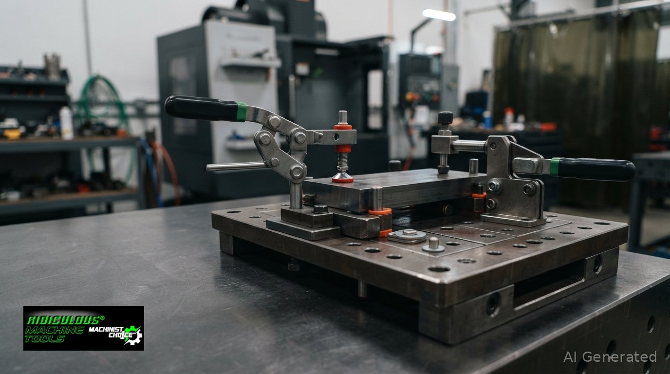
Effective toggle clamp alternatives for welding fixtures include horizontal-handle hold-down clamps and push-pull clamps. A horizontal clamp swings an arm over the workpiece, while a push-pull clamp applies force along a plunger’s axis. These different motions affect fixture layout, workpiece access, and force direction.
The right option depends on fixture geometry and the welding sequence. Compare how each mechanism moves, where it can be mounted, and how it will restrain the workpiece.
Key Takeaways
- Choose a horizontal-handle hold-down clamp when a swinging arm can reach over the workpiece without blocking loading or weld access.
- Use a push-pull straight-line clamp when the fixture needs force along a plunger’s axis rather than downward pressure from an arm.
- Read holding capacity and clamping force as different measures; the stated holding capacity accounts for a 2:1 safety factor.
- Match clamp style to the direction of restraint, available mounting space, and access needed during the welding sequence.
Horizontal-handle hold-down clamps
A horizontal-handle hold-down clamp keeps its handle generally horizontal when locked, while its clamping arm swings over the workpiece. This arrangement can suit low-clearance layouts where an upright handle would obstruct access. For example, a clamp beside a welded bracket can press a tab toward the fixture plate while keeping the handle out of the operator’s path. Check the clamp’s reach, arm travel, and mounting position to ensure the pad contacts a suitable area.
During loading, the operator raises the handle, swings the arm clear, positions the workpiece against its locators, then closes the arm over the part. The toggle linkage moves through its travel and locks over center when correctly adjusted. A threaded spindle and contact pad can help accommodate differences in workpiece height, but their available adjustment depends on the selected clamp. Keep the pad on a supported area; pressing near an unsupported edge can distort thin sheet or move a tack-welded component. The horizontal toggle clamp selection can be compared by base arrangement, arm reach, spindle configuration, and stated holding capacity.
A vertical-handle hold-down clamp also swings an arm over the workpiece, but its handle stands generally upright when locked. It can suit fixtures with open space above the base and a clear operator approach. However, the handle may interfere with a welding torch, fixture wall, or stacked component. Before mounting the clamp, check the full handle sweep: it may clear the workpiece when open but collide with nearby tooling when closed.
- Check that the arm reaches the clamping point without crossing the weld seam.
- Position the pad over a supported surface, such as a fixture stop or backing plate.
- Leave clearance for handle movement, part loading, and torch access.
Choose a horizontal-handle model for a low-clearance layout or a vertical-handle model when there is clear overhead access. With either style, align the clamp so it holds the part against the fixture locators rather than pulling it out of position.
Plunger-type push/pull clamps
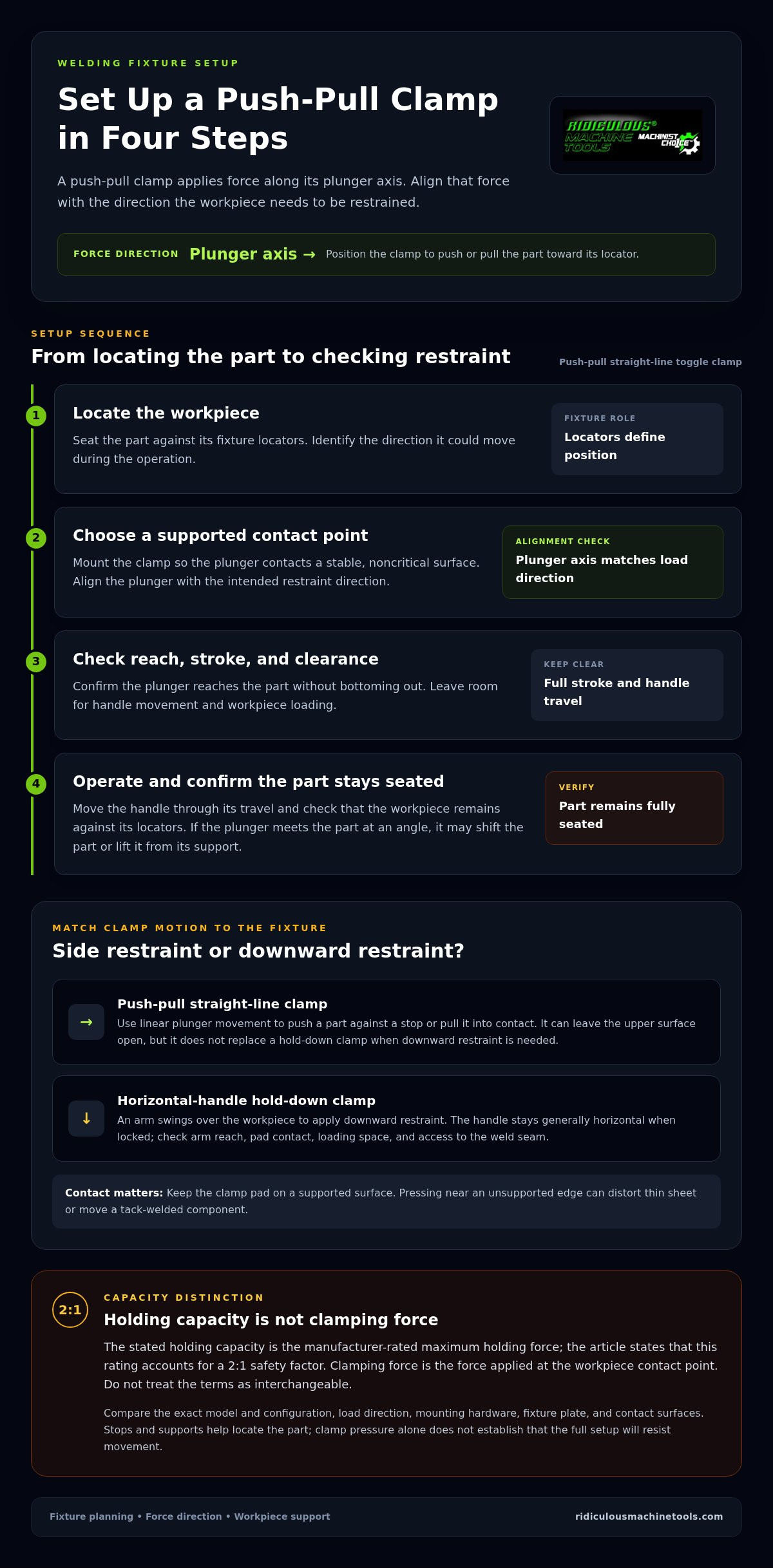
A push-pull straight-line toggle clamp converts handle movement into linear plunger travel. Unlike a hold-down arm, the plunger applies force along its own axis. Mount it beside a workpiece to push a flange against a locating stop, or opposite the stop to pull a component into contact. The clamp’s orientation and plunger travel determine the force direction, so alignment is essential.
On a welding fixture, a push-pull clamp can restrain a part from the side while leaving its upper surface open for torch access. For example, a plunger can press a tube against a fixed V-block during tack welding. The block locates the tube; the clamp maintains contact. If the plunger meets the tube at an angle, it may shift the part or lift it from its support. Align the plunger with the intended restraint direction.
Plan the mounting position around the clamp’s full stroke and handle movement. A practical setup sequence is:
- Place the workpiece against its fixture locators and identify the direction it could move.
- Position the clamp so the plunger contacts a supported, noncritical surface.
- Check that the plunger reaches the part without bottoming out or obstructing loading.
- Operate the handle and confirm the part stays seated against its locators.
Check the contact geometry. A flat plunger end may suit a broad, stable surface; a swivel foot can accommodate angled contact when included with the selected clamp. Models can differ in spindle, foot, stroke, and locking arrangement, so compare those features with the fixture’s space and the workpiece contact point. A push-pull clamp can secure a part against a stop, but it cannot replace a hold-down clamp when downward restraint is needed. Match the force direction to the part’s likely movement during welding.
What are the holding capacities and clamping forces of alternative toggle clamps?
Holding capacity and clamping force describe different limits. A toggle clamp’s stated holding capacity is its manufacturer-rated maximum holding force, and toggle-clamp holding capacity includes a 2:1 safety factor. Clamping force is the force the clamp applies to the workpiece at its contact point. Don’t treat the two terms as interchangeable when comparing clamp models or planning a fixture.
Choose a clamp for the workpiece’s mass, orientation, contact location, and required restraint direction. Holding a flat plate against a fixture surface creates a different load path from restraining a vertical tube with a side-mounted clamp. Stops and supports also carry loads. A clamp’s rating alone does not establish whether the full setup will resist movement; consider the mounting hardware, fixture plate, and contact surfaces too.
Compare the capacity rating for the exact clamp model and configuration. Base style, spindle arrangement, and clamp geometry can affect the stated capacity. Then consider how the workpiece loads the clamp during loading, tacking, and repositioning. For example, a long panel extending beyond a fixture support can create leverage at the contact point. Moving the clamp closer to a supported area may reduce unwanted movement more effectively than simply choosing a higher-rated model.
- Match the clamp’s rated holding capacity to the load direction and workpiece position.
- Check the mounting bolts and fixture plate as part of the load path.
- Use stops and supports to locate the part, rather than relying on clamp pressure alone.
- Keep the clamp pad on a stable surface to avoid slipping or deforming thin stock.
When comparing models, record capacity, force direction, mounting style, and spindle contact arrangement together. A higher holding-capacity figure does not automatically mean more useful force at the workpiece. On a tube fixture, for example, a correctly aligned clamp pressing against a locating stop may restrain the part more effectively than an offset clamp with a higher published rating. Choose capacity and geometry for the actual load path.
Which toggle clamp styles work best for welding fixtures: horizontal, vertical, push-pull, or latch?
No single toggle clamp style suits every welding fixture. Choose according to the workpiece’s restraint needs, available operating clearance, and loading sequence. Horizontal- and vertical-handle hold-down clamps apply pressure through an arm. Push-pull clamps move a plunger along its axis. Latch clamps pull mating components together.
A horizontal-handle clamp can fit a station with limited overhead space, while a vertical-handle clamp may suit a layout with clear space above the mounting base. For either style, map the handle’s full travel and the arm’s contact area before finalizing the fixture. This helps avoid interference with part loading and torch positioning.
Use a push-pull clamp when a part needs restraint from the side or end. A latch clamp serves a different purpose: its hook or similar engagement secures mating fixture components. Choose based on where the part needs support and how the clamp connects to the fixture.
- For an arm-style clamp, check its reach and clearance through the full operating cycle.
- For a plunger clamp, align its travel with the intended restraint direction.
- For a latch clamp, confirm that the hook engages the mating feature during closure.
- For any style, preserve access to the workpiece and weld area.
Before drilling mounting holes, sketch the clamp position, workpiece contact point, and operator approach. Then check the layout with the clamp both open and locked. A combination of clamp styles may suit a fixture with distinct restraint points, provided each clamp’s action matches its assigned location. Compare the available manual toggle clamp styles against that layout.
Ridiculous Machine Tools: Horizontal Toggle Clamps
Ridiculous Machine Tools offers toggle clamp styles for fixtures that need downward, lateral, or latching restraint. Compare the horizontal toggle clamps with vertical hold-down, push-pull straight-line, and latch toggle clamps by their action and fixture layout.
To choose an alternative to a Carr Lane toggle clamp for a welding fixture, start with the required force direction and available clearance. A horizontal- or vertical-handle hold-down clamp uses an arm over the workpiece; a push-pull model moves a plunger along its axis; a latch clamp draws mating components together. Compare the stated holding capacity, base style, and spindle configuration with the mounting position and contact point. These criteria help narrow the choice without assuming every clamp suits every fixture.
Visit Ridiculous Machine Tools online to compare available toggle clamp styles.
FAQs
How can I reduce weld spatter exposure on a toggle clamp?
Where the layout allows, position the clamp outside the direct path of spatter. Keep moving joints and contact surfaces clear of debris that could interfere with clamp travel or seating.
Can one fixture accommodate parts with different thicknesses?
It depends on the clamp’s spindle adjustment, arm reach, and usable travel. Compare these features with the workpiece range, and make sure each part still seats against its locators.
Why might a workpiece shift as the clamp closes?
The clamp may be applying force that moves the part away from its locating surfaces. Review the contact point and locator arrangement, then adjust the setup so the part stays seated as the clamp closes.
Should toggle clamps locate a welding part?
Use fixture stops and locators to establish the part’s position. A toggle clamp provides restraint; relying on its contact pad alone to locate the part can make placement less consistent.
Article by
Ridiculous Machine Tools Technical Team
The Ridiculous Machine Tools Technical Team provides practical information about precision machine tooling, CNC tooling, workholding, and related manufacturing applications. RMT focuses on helping machinists, manufacturers, fabricators, and other customers understand tooling specifications, compatibility, selection, and proper application. Our technical content draws on product specifications, industry knowledge, and RMT's quality-control experience to provide clear, useful information for selecting and using machine tooling and workholding products.
Ridiculous Machine Tools — Machinist's Choice™